

Solar cell module and method for producing solar cell module
A technology of solar cells and sub-modules, applied in the direction of electrolytic capacitors, final product manufacturing, sustainable manufacturing/processing, etc., can solve problems such as difficult wiring operations, achieve the effects of suppressing leakage and preventing the reduction of power generation efficiency
- Summary
- Abstract
- Description
- Claims
- Application Information
AI Technical Summary
Problems solved by technology
Method used
Image

Examples
no. 1 approach
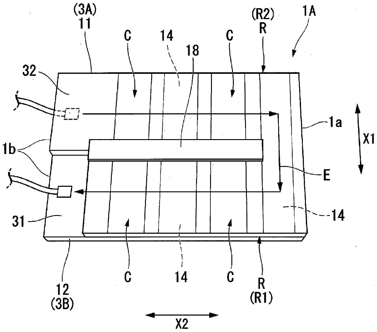
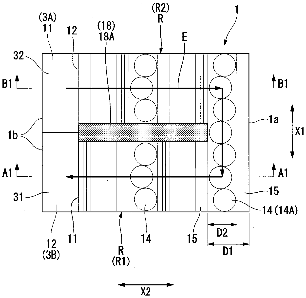
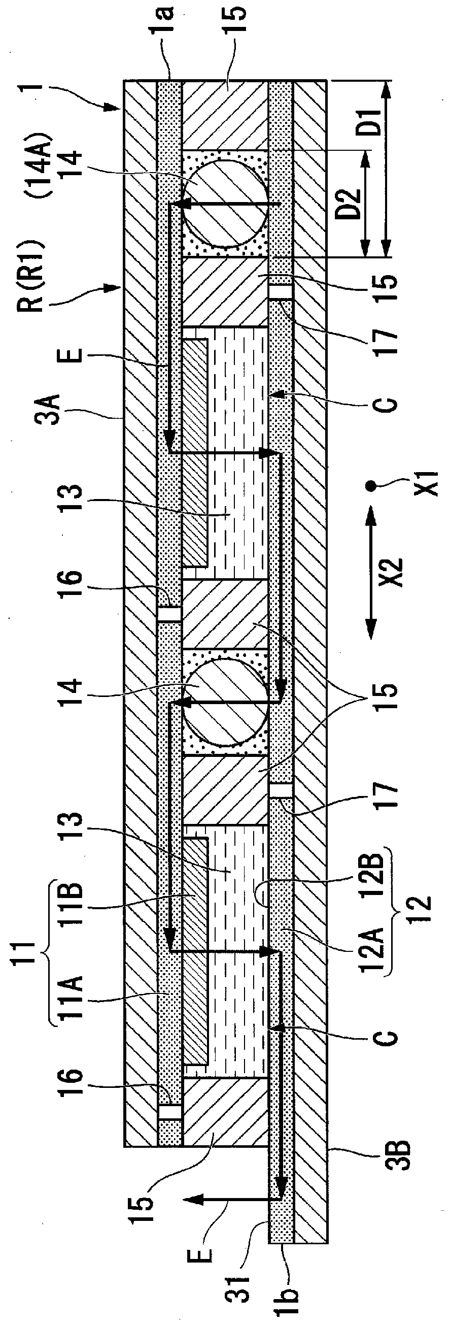
[0075] Such as figure 1 as well as figure 2 As shown, the solar cell module 1 of the first embodiment of the present invention is prepared by the following roll-to-roll method (hereinafter referred to as the R to R method), which is a thin-film type elongated in the first direction (length direction X1). The dye-sensitized solar cell is manufactured by cutting it to a specific length. The solar cell module 1 has a battery structure in which two blocks (submodules R, R) composed of a plurality of cells C arranged in a width direction X2 (second direction) orthogonal to the longitudinal direction X1 when viewed from above are adjacent in the longitudinal direction X1 , The adjacent sub-modules R and R are electrically connected at one end 1a side of the width direction X2.
[0076] in figure 1 and figure 2 In the figure, the arrow indicates the flow of current, and the symbols + (positive) and-(negative) indicate the positive electrode and the negative electrode, respectively (...
no. 2 approach
[0131] Such as Image 6 As shown, the dye-sensitized solar cell 101 (solar cell module) of the second embodiment is prepared in the first direction (length direction X1) according to the following roll-to-roll method (hereinafter referred to as R to R method) The long-stretched thin-film dye-sensitized solar cell is manufactured by cutting it to a specific length.
[0132] in Image 6 In the middle, the arrow indicates the direction of current flow ( Figure 7 The same is true), and the symbols + (positive) and-(negative) respectively indicate the positive electrode and the negative electrode (the same applies to other figures).
[0133] Here, in the dye-sensitized solar cell 101, as described above, the longitudinal direction X1 is set as the arrangement direction of the submodules R, and the width direction X2 is set as a direction orthogonal to the longitudinal direction X1 in a plan view, and these are collectively used below.
[0134] Such as Figure 7 As shown, the dye-sensitiz...
no. 3 Embodiment approach
[0182] Figure 20 The dye-sensitized solar cell 101A of the second embodiment shown is a battery structure in which two blocks (submodules R, R) composed of a plurality of cells C arranged in the width direction X2 are adjacent to each other in the length direction X1. The adjacent submodules R and R are electrically connected to each other on the side of one end 101a in the width direction X2.
[0183] The ultrasonic fusion part 118 extends from the other end 1b to the one end 101a side in a state where the wiring material 119 on the one end 101a side is left in the width direction X2 of each submodule R, R. Thereby, a circuit in which the photoelectrode 111 and the counter electrode 112 of each of the submodules R and R are electrically connected through the wiring material 119 is formed.
[0184] In the third embodiment, the sub-modules R and R on the one end 1a side of the longitudinal direction X1 are electrically connected to each other by the wiring material 119, and the end...
PUM
| Property | Measurement | Unit |
|---|---|---|
| Width size | aaaaa | aaaaa |
| Length | aaaaa | aaaaa |
Abstract
Description
Claims
Application Information