
Fireproof material heat insulation layer spraying device

A technology of spraying device and fireproof material, which is applied in the direction of spraying device and liquid spraying device, etc. It can solve the problems of reducing the efficiency of spraying, inconvenient spraying treatment, inconvenient handling of fireproof materials, etc., and achieves simple design structure, uniform and efficient spraying, and uniform moving speed Effect

Inactive Publication Date: 2021-09-17
吕浩
View PDF0 Cites 1 Cited by
  • Summary
  • Abstract
  • Description
  • Claims
  • Application Information

AI Technical Summary

Problems solved by technology

[0004] The purpose of the present invention is to provide a spraying device for fireproof material heat insulation layer, to solve the problem in the above-mentioned background technology that when spraying heat insulation layer on the surface of the present fireproof material, the material needs to be transported to the inside of the designated equipment. It is fixed and then sprayed. When the volume of the fireproof material is large and it is not convenient to carry it and it is not convenient to spray it, and the current spraying equipment is large in size and is not conducive to handling and moving operations, and it does not have a multi-directional adjustment structure. The area of ​​spraying is limited to a certain extent, which is not conducive to the surface spraying treatment of the current fireproof materials, which greatly reduces the efficiency of spraying

Method used


Image

  • Fireproof material heat insulation layer spraying device
  • Fireproof material heat insulation layer spraying device
  • Fireproof material heat insulation layer spraying device

Examples


Embodiment Construction

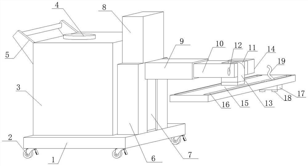
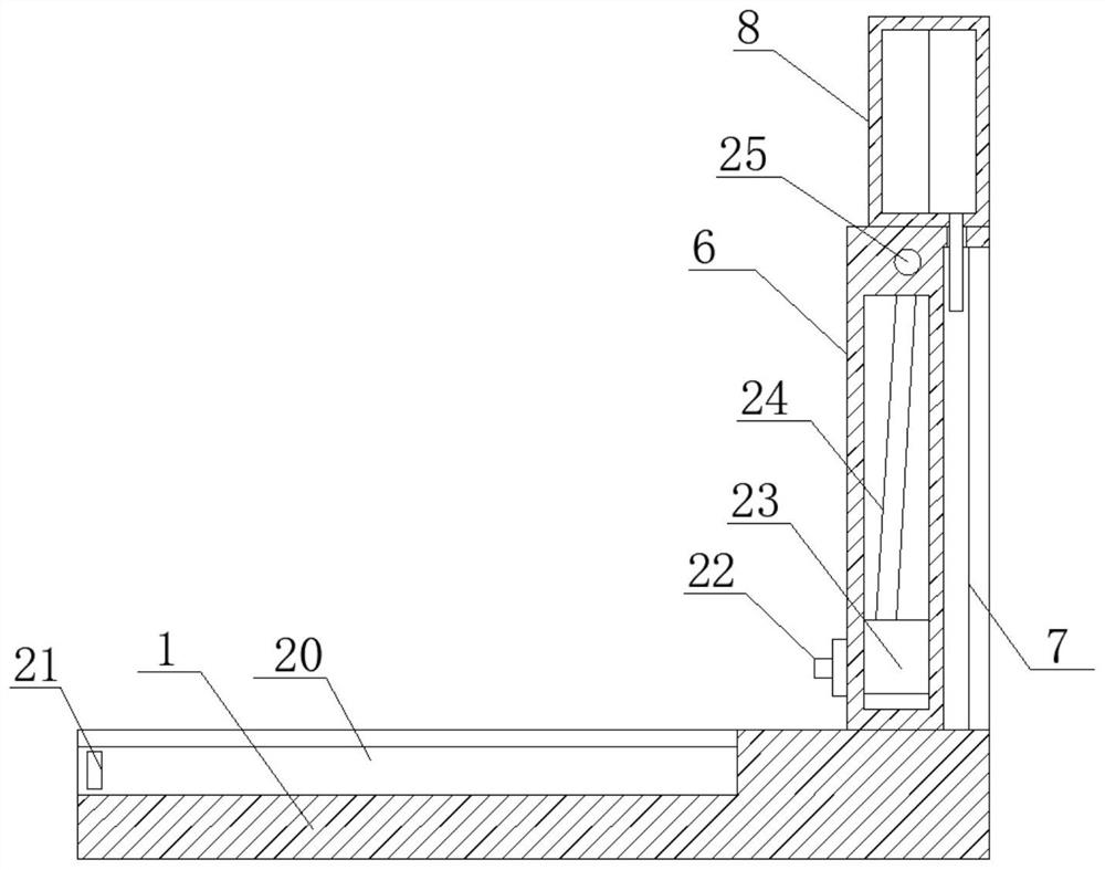
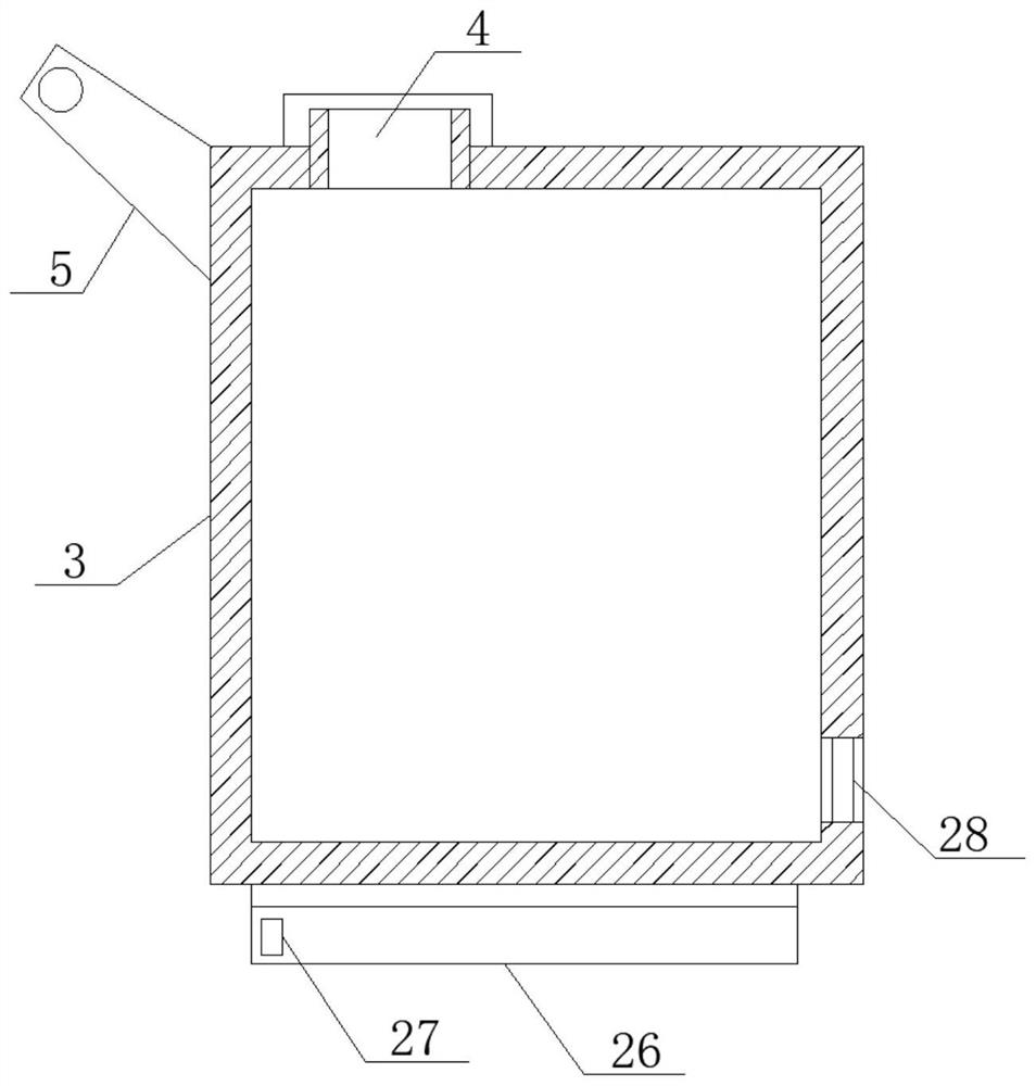
[0026] see Figure 1-2, in the embodiment of the present invention, a kind of spraying device of fireproof material heat insulation layer, comprises fixed bottom plate 1, and the bottom surface bolt of fixed bottom plate 1 is connected with moving roller 2, and the top surface of fixed bottom plate 1 is connected with main material storage box 3, The top surface of the main storage box 3 is provided with a feed pipe 4, and one side of the main storage box 3 is obliquely welded with a push rod 5, and the number of moving rollers 2 is four, and the four moving rollers 2 are fixedly arranged respectively. At the four corners of the bottom surface of the fixed bottom plate 1, the sides of the four moving rollers 2 are provided with brake structures. Keep connected with the inside of the main storage box 3, the push rod 5 is fixed on the top of the side of the main storage box 3 away from the side vertical rod 6, and the top surface of the fixed bottom plate 1 is vertically upwardl...


PUM


Abstract

The invention discloses a fireproof material heat insulation layer spraying device, and relates to the field of fireproof materials. The device comprises a fixed bottom plate, wherein the bottom surface of the fixed bottom plate is in bolted connection with moving rollers, the top surface of the fixed bottom plate is in butt joint with a main material storage box, the top surface of the main material storage box is provided with a feeding pipe, a pushing rod is obliquely welded to one side edge of the main material storage box, a side vertical rod is vertically and upwards in bolted connection with the top surface of the fixed bottom plate, a side clamping groove is vertically formed in the side edge, away from the main material storage box, of the side vertical rod, a pushing air cylinder is in bolted connection with the top end of the side vertical rod, and the side edge, away from the main material storage box, of the side vertical rod is horizontally in butt joint with a movable sleeve rod. The device is simple in design structure and convenient to operate, subsequent disassembly is facilitated by adopting a buckling mode for connection, meanwhile, spraying work under various conditions can be conducted by adopting a multi-angle adjusting structure, and spraying is more uniform and efficient due to movement at a constant speed.

Description

technical field [0001] The invention relates to the technical field of fireproof materials, in particular to a spraying device for heat insulation layers of fireproof materials. Background technique [0002] Fireproof materials are materials that prevent or retard the spread of flames. Used for fire prevention. There are two types of non-combustible materials and flammable materials. Noncombustible materials do not burn. Although flame-retardant materials can be burned, they are flame-retardant, that is, they are difficult to catch fire and carbonize, and they can stop burning after the fire source is removed, so they are also called flame-retardant materials. Among the flame retardant materials, except for a few that have flame retardant function, in most cases, they are made by flame retardant treatment of flammable materials with flame retardants, fire impregnating agents or fire retardant coatings. From the perspective of fire safety, fireproof materials should be us...

Claims


Application Information

Patent Timeline
Patent Type & Authority Applications(China)
IPC IPC(8): B05B15/625B05B9/04
CPCB05B15/625B05B9/0403
Inventor 吕浩
Owner 吕浩
Learn More