
Vacuum suction cup type outer jolt ramming device for low-temperature storage tank

A technology of low-temperature storage tanks and vacuum suction cups, which is applied in the direction of containers, large containers, packaging, etc. It can solve the problems of destructive product particle size, inability to install vibrators, and affect product quality, etc., to achieve compact structure and ensure thermal insulation performance , the effect of convenient operation

Active Publication Date: 2021-09-17
泰有科技(无锡)有限公司
View PDF11 Cites 0 Cited by
  • Summary
  • Abstract
  • Description
  • Claims
  • Application Information

AI Technical Summary

Problems solved by technology

The traditional interlayer assembled vibrator has some shortcomings in use. First, personnel need to enter the top of the storage tank interlayer to install the vibrator before filling, which has a high risk factor and cumbersome assembly; secondly, the vibrator is inserted into the pearlite Vibration work is carried out inside the product, which is destructive to the product particle size and affects product quality; the third pair of low-temperature storage tanks that do not have steel beams suspended on the top of the interlayer, and the assembled vibrator in the interlayer cannot be installed for vibration

Method used


Image

  • Vacuum suction cup type outer jolt ramming device for low-temperature storage tank
  • Vacuum suction cup type outer jolt ramming device for low-temperature storage tank
  • Vacuum suction cup type outer jolt ramming device for low-temperature storage tank

Examples


Embodiment Construction

[0018] The specific implementation manner of the present invention will be described below in conjunction with the accompanying drawings.

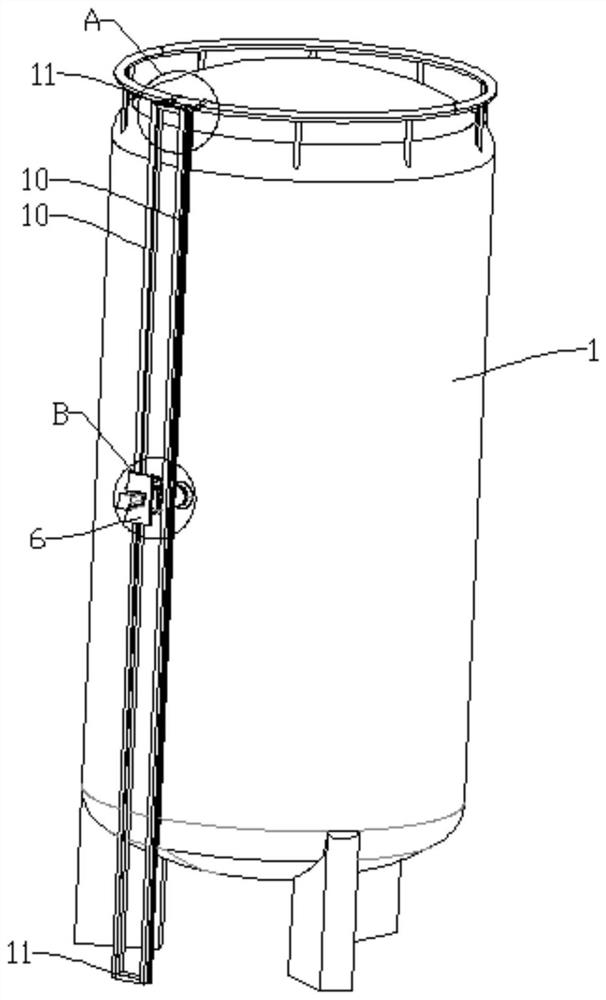
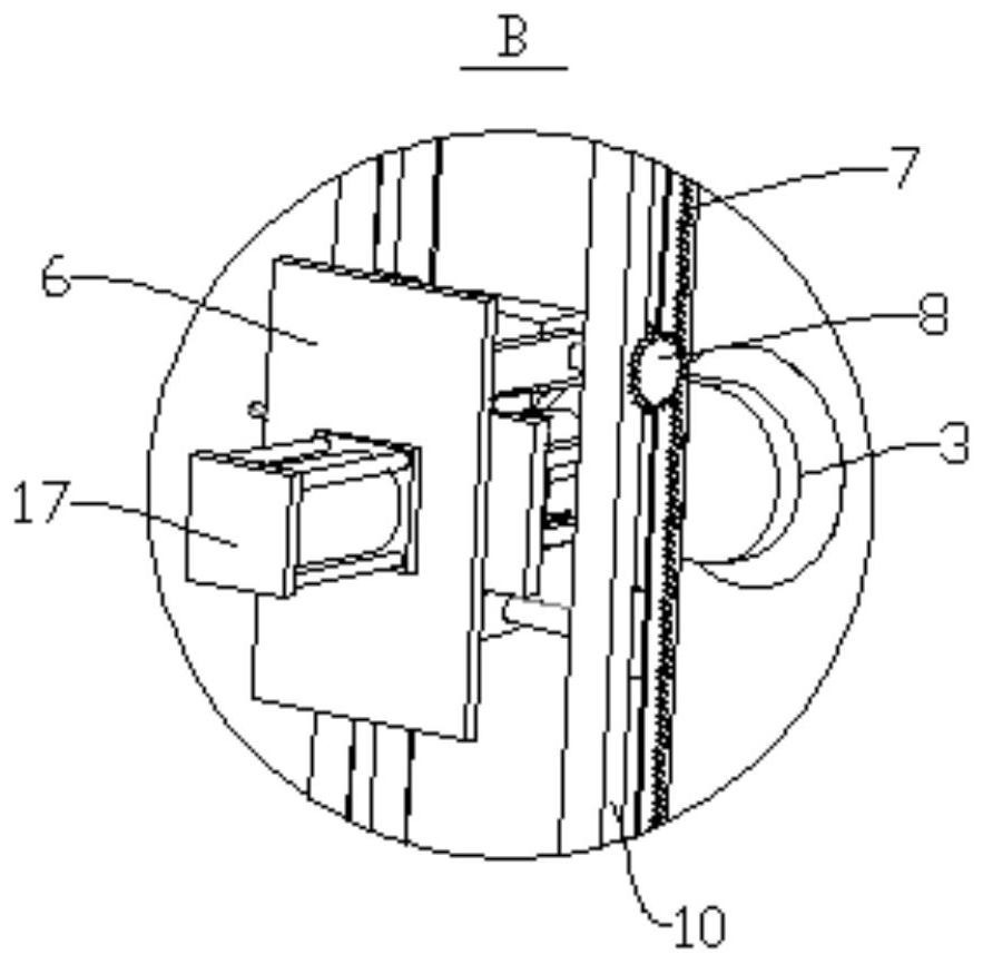
[0019] Such as figure 1 and image 3 In the shown embodiment, it mainly includes two hangers 10 symmetrically arranged left and right, and a lifting frame 6 capable of sliding up and down is arranged between the two hangers 10 . The front end of the lifting frame 6 is provided with a vibrating component, which can realize the vibration of the material in the cryogenic storage tank 1 .

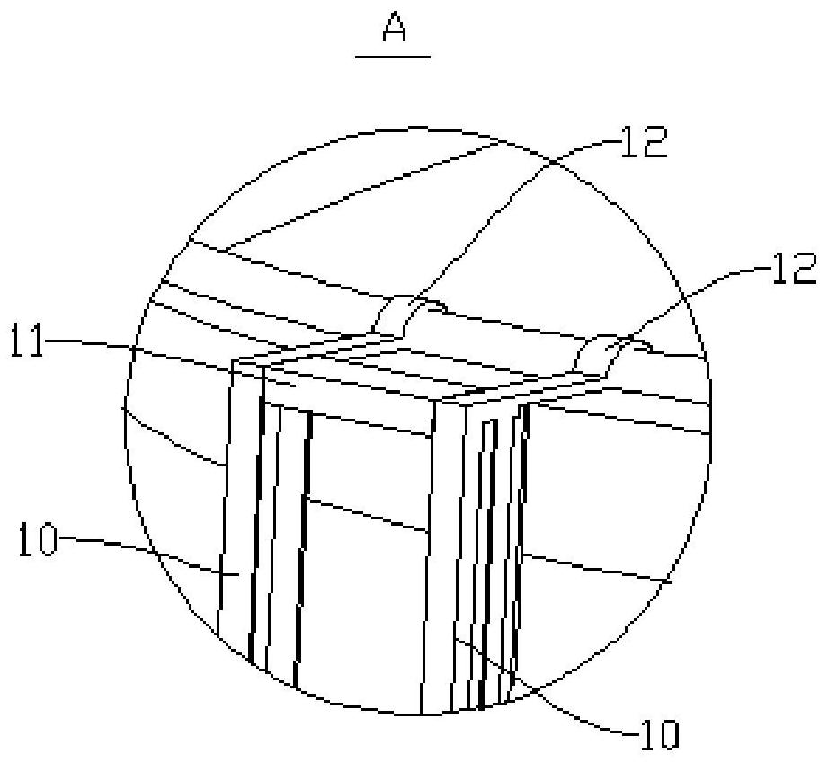
[0020] Such as figure 1 and figure 2 In the shown embodiment, crossbars 11 are arranged between the upper and lower parts of the two hangers 10, and the two hangers 10 are welded to both ends of the crossbars 11 respectively.

[0021] In order to facilitate the installation of the hanger 10 on the cryogenic storage tank 1, as figure 1 and figure 2 In the shown embodiment, the upper front ends of the two hangers 10 are respectively welded with hooks ...


PUM


Abstract

The invention relates to the technical field of low-temperature storage tank jolt ramming, in particular to a vacuum suction cup type outer jolt ramming device for a low-temperature storage tank. The device comprises two hanging frames which are symmetrically arranged left and right, a lifting frame capable of sliding up and down is arranged between the two hanging frames, a jolt ramming assembly is arranged on the front end face of the lifting frame, two front mounting frames are fixed to the upper portion of the front end face of the lifting frame, a double-shaft motor is arranged between the two front mounting frames, two output ends of the double-shaft motor are connected with driving wheels correspondingly, a rear mounting frame is fixed to the lower portion of the front end face of the lifting frame, the rear mounting frame is rotationally connected with a driven wheel shaft, and two ends of the driven wheel shaft are connected with driven wheels respectively. According to the device, jolt ramming is carrying out on internal accumulated materials outside the low-temperature storage tank, so that the air content among the materials in the storage tank is greatly reduced, the heat insulation performance is greatly improved, and the safety of material storage is improved; and the device can be hung at any position of the low-temperature storage tank, and can be adjusted at any height position on the surface of the low-temperature storage tank through a lifting mechanism, so that jolt ramming can be carried out on the whole tank.

Description

technical field [0001] The invention relates to the technical field of low-temperature storage tank vibration, in particular to a vacuum suction cup type external vibrator for low-temperature storage tanks. Background technique [0002] The interlayer of large-scale low-temperature storage tanks is filled with pearlite. In order to ensure that the filling density meets the design requirements and the effect of cold preservation, the interlayer pearlite must be vibrated during the filling process. [0003] In the prior art, most cryogenic storage tanks are compacted by an assembled vibrator in the interlayer. The traditional interlayer assembled vibrator has some shortcomings in use. First, personnel need to enter the top of the storage tank interlayer to install the vibrator before filling, which has a high risk factor and cumbersome assembly; secondly, the vibrator is inserted into the pearlite The internal vibration work of the product is very destructive to the product p...

Claims


Application Information

Patent Timeline
IPC IPC(8): B65D90/00
CPCB65D90/00
Inventor 林海威孙峰
Owner 泰有科技(无锡)有限公司
Learn More