
Automatic cleaning equipment for stock bin

A technology of automatic cleaning and cleaning equipment, which is applied in the direction of grain processing, cleaning hollow objects, cleaning methods and utensils, etc., which can solve the problems of manual cleaning danger, reduced silo capacity, and easy hardening of incoming materials, so as to solve the problems that are difficult to clean and avoid Ineffective work and the effect of improving efficiency

Active Publication Date: 2021-09-17
HUANENG ZUOQUAN COAL&POWER CO LTD
View PDF22 Cites 2 Cited by
  • Summary
  • Abstract
  • Description
  • Claims
  • Application Information

AI Technical Summary

Problems solved by technology

[0003] However, after several years of actual use, the accumulated sticky material on the inner wall of the silo caused the incoming materials above the activated feeder to fail to obtain vibration energy. The capacity is reduced, and at the same time, the accumulation of material in the silo is prone to deterioration. The prior art cleaning of the silo has the problems of difficulty in cleaning the accumulation of material in the silo, danger of manual cleaning, or slow fatigue of manual cleaning equipment.

Method used


Image

  • Automatic cleaning equipment for stock bin
  • Automatic cleaning equipment for stock bin
  • Automatic cleaning equipment for stock bin

Examples


Embodiment Construction

[0030] The present invention will be further described below in conjunction with the accompanying drawings and embodiments.

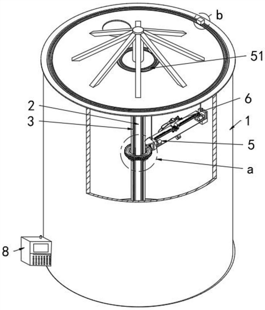
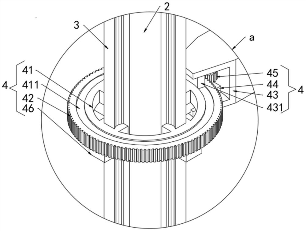
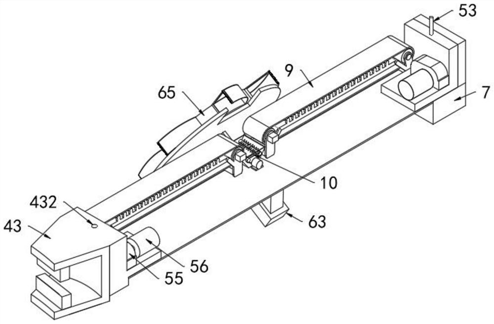
[0031] Please refer to Figure 1 to Figure 9 ,in, figure 1 A schematic structural view of a preferred embodiment of the automatic bin cleaning equipment provided by the present invention; figure 2 for figure 1 A partial enlarged view of a shown; image 3 for figure 1 Schematic diagram of the structure of the cleaning assembly shown; Figure 4 for figure 1 A structural schematic diagram of another viewing angle of the shown cleaning assembly; Figure 5 for image 3 The structural schematic diagram of the wheel bucket shown; Figure 6 for image 3 The structural schematic diagram of the mobile car shown; Figure 7 for figure 1 A partial enlarged view of b shown; Figure 8 for figure 1 The structural schematic diagram of the lift assembly shown; Figure 9 for Figure 8 The schematic diagram of the structure of the trolley is shown. It incl...


PUM


Abstract

The invention provides automatic cleaning equipment for a stock bin. The automatic cleaning equipment for the stock bin comprises a stock bin shell, a bearing column, a guide rail, a rotating assembly, a lifting assembly, a cleaning assembly, a detection assembly and a controller assembly, the rotating assembly used for driving the cleaning equipment to rotate for cleaning is installed on the guide rail, the lifting assembly used for driving the cleaning equipment to ascend and descend is installed on the rotating assembly and the stock bin shell, the cleaning assembly used for cleaning the inner wall of the stock bin shell is installed on the rotating assembly, the detection assembly used for detecting the material accumulation condition of the inner wall of the stock bin shell is installed on the rotating assembly, and the controller assembly used for controlling the cleaning equipment to operate is installed on the stock bin shell. The material accumulation condition of the inner wall of the stock bin shell is detected through the detection assembly and then fed back to the controller assembly, the controller assembly controls the rotating assembly, the lifting assembly and the cleaning assembly to clean the stock bin on the inner wall of the stock bin in a dead-angle-free, full-automatic, rapid and continuous mode, and reliable and safe guarantee is provided for personnel safety and work progress.

Description

technical field [0001] The invention relates to the technical field of silo cleaning, in particular to automatic cleaning equipment for silos. Background technique [0002] The silo is a container for storing materials, usually a steel structure or a reinforced concrete structure. The geometric shape of the silo: the upper part is mostly cylindrical or prismatic, and the lower part shrinks into a conical funnel with a discharge port. There are 4 activated feeders under the warehouse, and the vibration system of the activated feeder is composed of a vibration motor and a vibration spring. It uses the principle of sub-resonance two-mass vibration, and the excitation force of a small-power motor drives the main tank to obtain the required linear amplitude. The damping effect applied by the material to the feeder will actually increase the discharge capacity. When the load increases, the natural frequency of the discharger will decrease slightly, so that the frequency ratio wi...

Claims


Application Information

Patent Timeline
Patent Type & Authority Applications(China)
IPC IPC(8): B65D90/00B65D88/28B65D90/48B65D90/02B08B9/087B65G15/32B65G35/00B02C23/02
CPCB65D90/0093B65D88/28B65D90/48B65D90/02B08B9/087B65G15/32B65G35/00B02C23/02
Inventor 华一凡李海平叶冲郜旭鹏王锦绣王志国闫海鹏苏铎李赟兰保国
Owner HUANENG ZUOQUAN COAL&POWER CO LTD
Learn More