Batch wire arranging device for braided wire winding

A cable arrangement and braided wire technology, applied in the directions of transportation and packaging, transportation of filamentous materials, thin material handling, etc. Effect

Pending Publication Date: 2021-09-17
安徽天元塑业有限公司
View PDF0 Cites 2 Cited by
  • Summary
  • Abstract
  • Description
  • Claims
  • Application Information

AI Technical Summary

Problems solved by technology

[0004] The purpose of the present invention is to solve the problem of inconvenient movement and use in the prior art, and propose a batch wire arranging device for braided wire winding

Method used


Image

  • Batch wire arranging device for braided wire winding
  • Batch wire arranging device for braided wire winding
  • Batch wire arranging device for braided wire winding

Examples


Embodiment 1

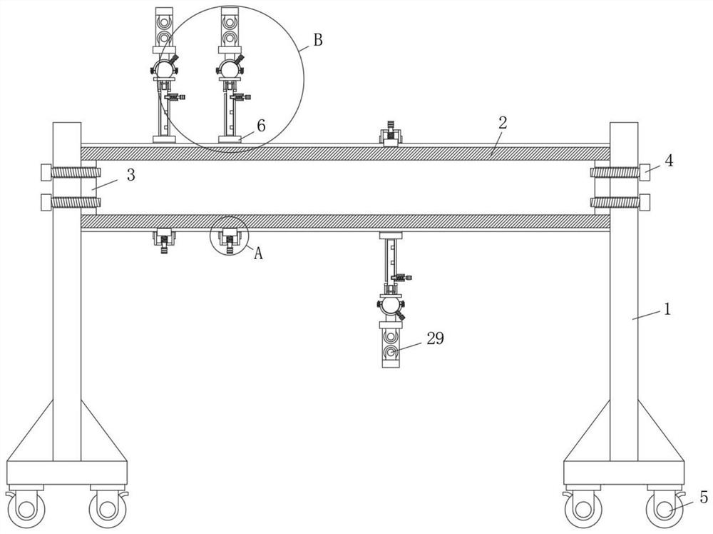
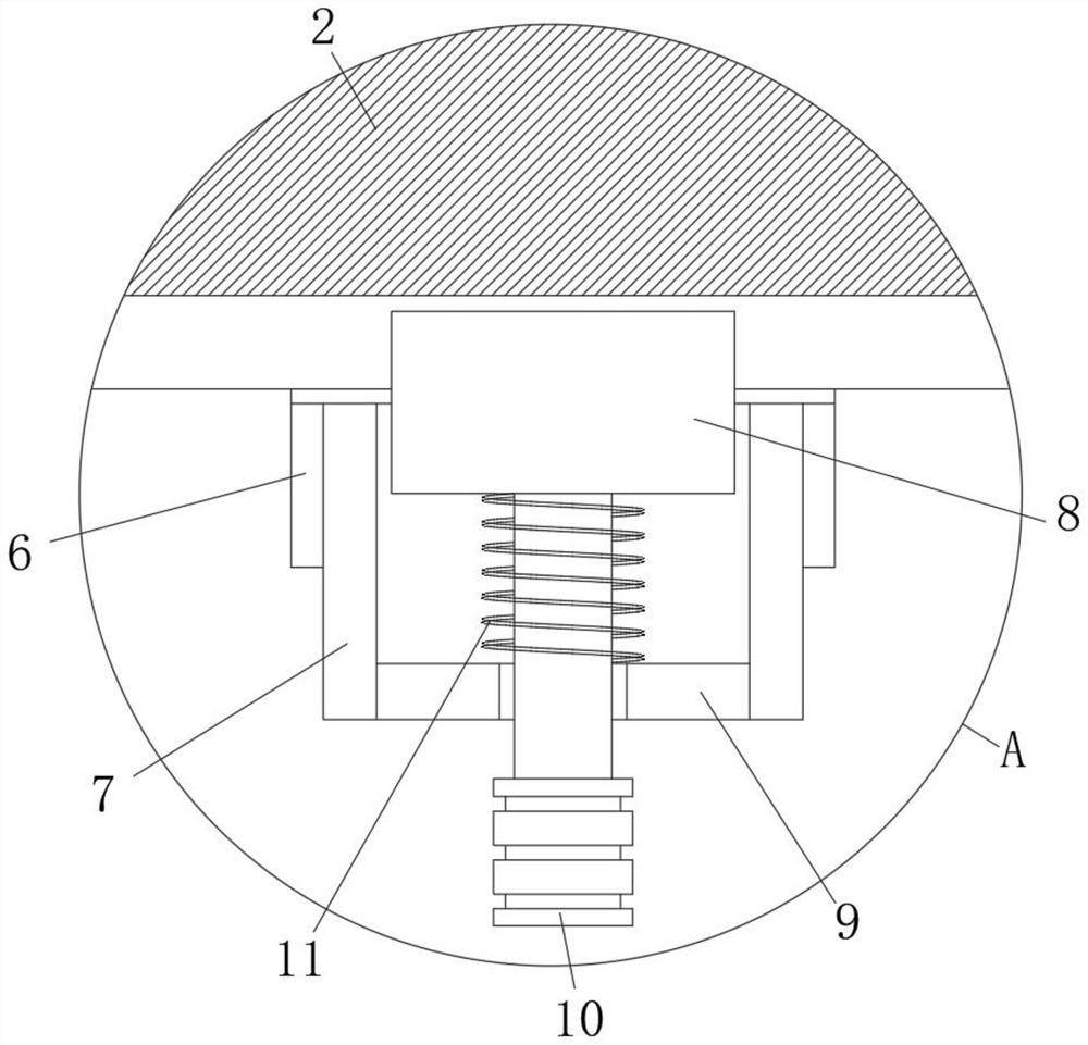
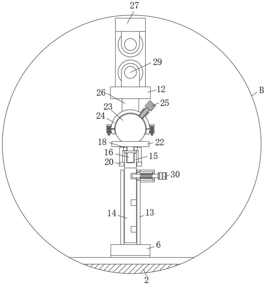
[0031] refer to Figure 1-5 , a batch wiring device for braided wire winding, comprising two vertically parallel vertical plates 1, a circular shaft tube 2 is arranged between the two vertical plates 1, and a sleeve is provided on the outer side of the circular shaft tube 2 for rotation 6. There is a fixing mechanism between the sleeve 6 and the cylindrical shaft 2, and one side of the sleeve 6 is provided with an installation end plate 12, and an adjustment mechanism is provided between the installation end plate 12 and the sleeve 6, and the installation end plate 12 is far away from One side of the casing 6 is provided with a U-shaped coaming plate 27, and the inner side of the U-shaped coaming plate 27 and the side where the end plate 12 is installed are symmetrically installed with a wire-passing roller 29;

[0032] The fixing mechanism includes a vertical tube 7 fixed on the tube wall of the casing 6. The outer side of the cylindrical shaft tube 2 is divergently provided ...

Embodiment 2

[0038] like Figure 1-5 As shown, this embodiment is basically the same as Embodiment 1. Preferably, the inner walls of both ends of the cylindrical shaft 2 are fixedly connected with the installation inner plate 3 , and a fixing bolt 4 is arranged between the installation inner plate 3 and the vertical plate 1 .

[0039] In this embodiment, it is easy to disassemble, so that the device can select a corresponding number of sleeves 6 according to the number of strands of the braided wire.

Embodiment 3

[0041] like Figure 1-5As shown, this embodiment is basically the same as Embodiment 1. Preferably, one end of the handle 10 slides through the inner side of the track ring 9 and is provided with anti-slip grooves.

[0042] In this embodiment, it is convenient for people to adjust the angle of the casing 6 .


PUM


Abstract

The invention discloses a batch wire arranging device for braided wire winding. The device comprises two vertical plates which are vertically arranged in parallel, a circular shaft barrel is arranged between the two vertical plates, the outer side of the circular shaft barrel is rotationally provided with a sleeve in a sleeving mode, a fixing mechanism is arranged between the sleeve and the circular shaft barrel, one side of the sleeve is provided with a installation end plate, an adjusting mechanism is arranged between the installation end plate and the sleeve, a U-shaped surrounding plate is arranged on one side, away from the sleeve, of the installation end plate, wire passing rollers are symmetrically installed on the inner side of the U-shaped surrounding plate and one side of the installation end plate, the fixing mechanism comprises a vertical cylinder fixed to the wall of the sleeve in a penetrating mode, a plurality of strip-shaped clamping grooves are formed in the outer side of the circular shaft barrel in a divergent mode, a pointed-end clamping plate is connected into the vertical barrel in a sliding mode, and a rail ring is fixedly connected to the inner wall of one end, away from the circular shaft barrel, of the vertical barrel. The device is convenient to use, high in applicability and practicability and convenient to move as a whole, and the use requirements of people in production and life are met.

Description

technical field [0001] The invention relates to the technical field of braided wire production, in particular to a batch wire arranging device for braided wire winding. Background technique [0002] Braided wires can be classified according to the number of strands, and can be classified into double strands, triple strands, quadruple strands, etc., and can also be classified by material. [0003] During the production process of the braiding line, the raw material line first protrudes from the raw material spool and passes through the wire arrangement device to guide the spatial distribution of the raw material. After passing through the guided raw material line, it is then wound in the winding device. The distribution of various raw material lines in the space is very critical. The existing line arrangement device needs to adjust the height of the support rods one by one in the process of distributing and arranging the raw material lines, which is relatively scattered and i...

Claims


Application Information

Patent Timeline
IPC IPC(8): B65H57/14B65H57/26B65H57/16B65H57/28
CPCB65H57/14B65H57/26B65H57/16B65H57/28
Inventor 沈长青
Owner 安徽天元塑业有限公司
Why Eureka
Try Eureka