River floating garbage collecting device
A garbage collection and river channel technology, applied in water conservancy projects, cleaning of open water surfaces, construction, etc., can solve the problems of slow cleaning efficiency and high labor intensity of staff, and achieve the effect of convenient fixing
- Summary
- Abstract
- Description
- Claims
- Application Information
AI Technical Summary
Problems solved by technology
Method used
Image

Examples
Embodiment 1
[0033] like figure 1 and figure 2 As shown, a river floating garbage collection device includes a fish-shaped frame 1, a rotating and swinging mechanism 2, a sliding mechanism 3 and an installation frame 4. The right side of the fish-shaped frame 1 is provided with a rotating and swinging mechanism 2, and the fish-shaped A sliding mechanism 3 is arranged inside the frame 1, and installation frames 4 are arranged on both front and rear sides of the middle part of the fish-shaped frame 1 .
[0034] When it is necessary to clean up river rubbish, the staff fixes the net for collecting rubbish on the installation frame 4 with a special tool, and then the staff places the device in the river, and then rotates the fish-shaped frame 1 through the rotating swing mechanism 2. Moving in the river, the garbage in the river enters the fish-shaped frame 1. At this time, the sliding mechanism 3 slides back and forth to move the garbage in the fish-shaped frame 1 to the installation frame ...
Embodiment 2
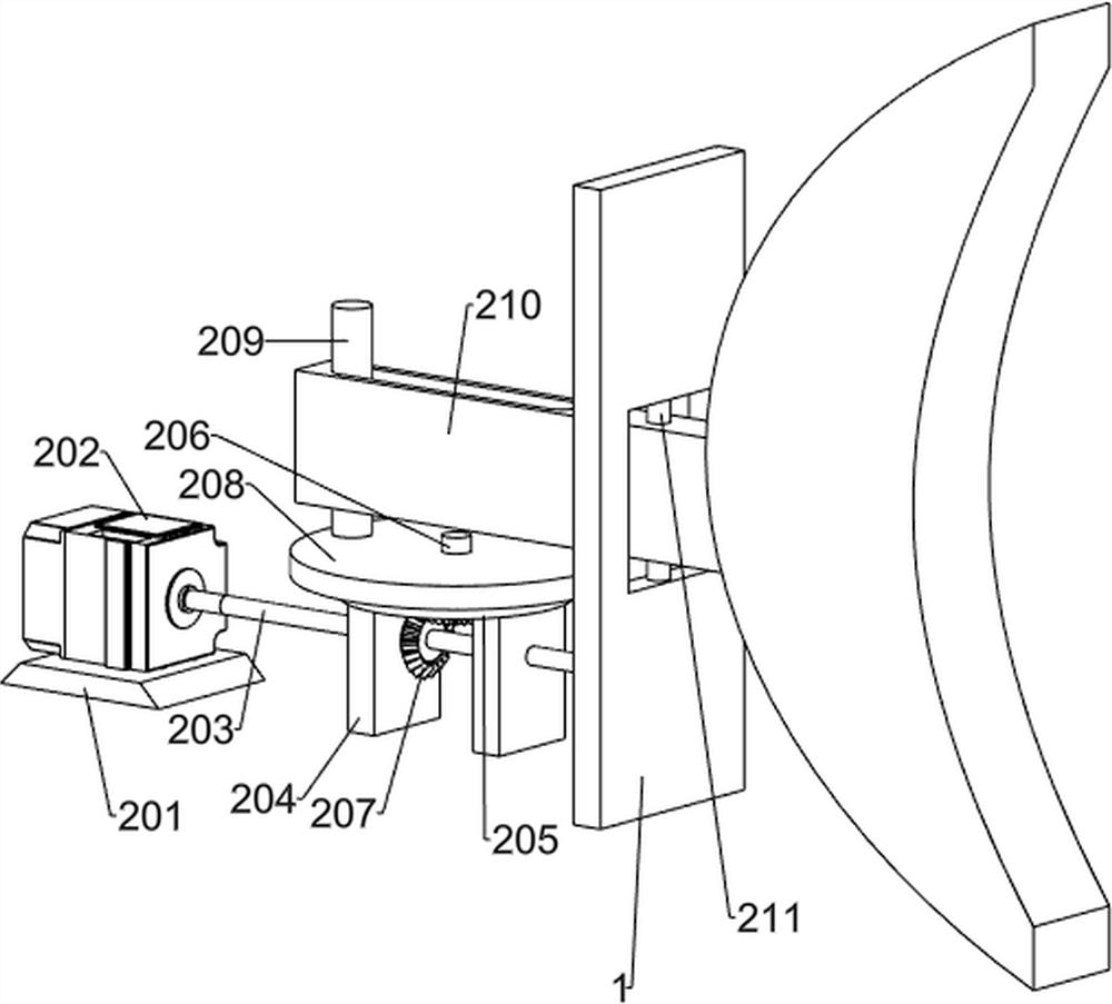
[0036] like image 3 and Figure 4As shown, on the basis of Embodiment 1, the rotary swing mechanism 2 includes a support base 201, a servo motor 202, a first rotating shaft 203, a bearing seat 204, a supporting disc 205, a second rotating shaft 206, a bevel gear assembly 207, and a turntable 208, rotating rod 209, swing plate 210 and straight rod 211, the right side of the fish-shaped frame 1 is provided with a support base 201, the support base 201 is provided with a servo motor 202, and the right side of the fish-shaped frame 1 is provided with a bearing seat 204, the first rotating shaft 203 is rotatably arranged on the bearing seat 204, the left end of the first rotating shaft 203 is connected with the output shaft of the servo motor 202 through a coupling, and the right side of the fish-shaped frame 1 is provided with a support plate 205, the first The right end of the rotating shaft 203 is rotatably connected to the supporting disc 205, the center of the supporting dis...
Embodiment 3
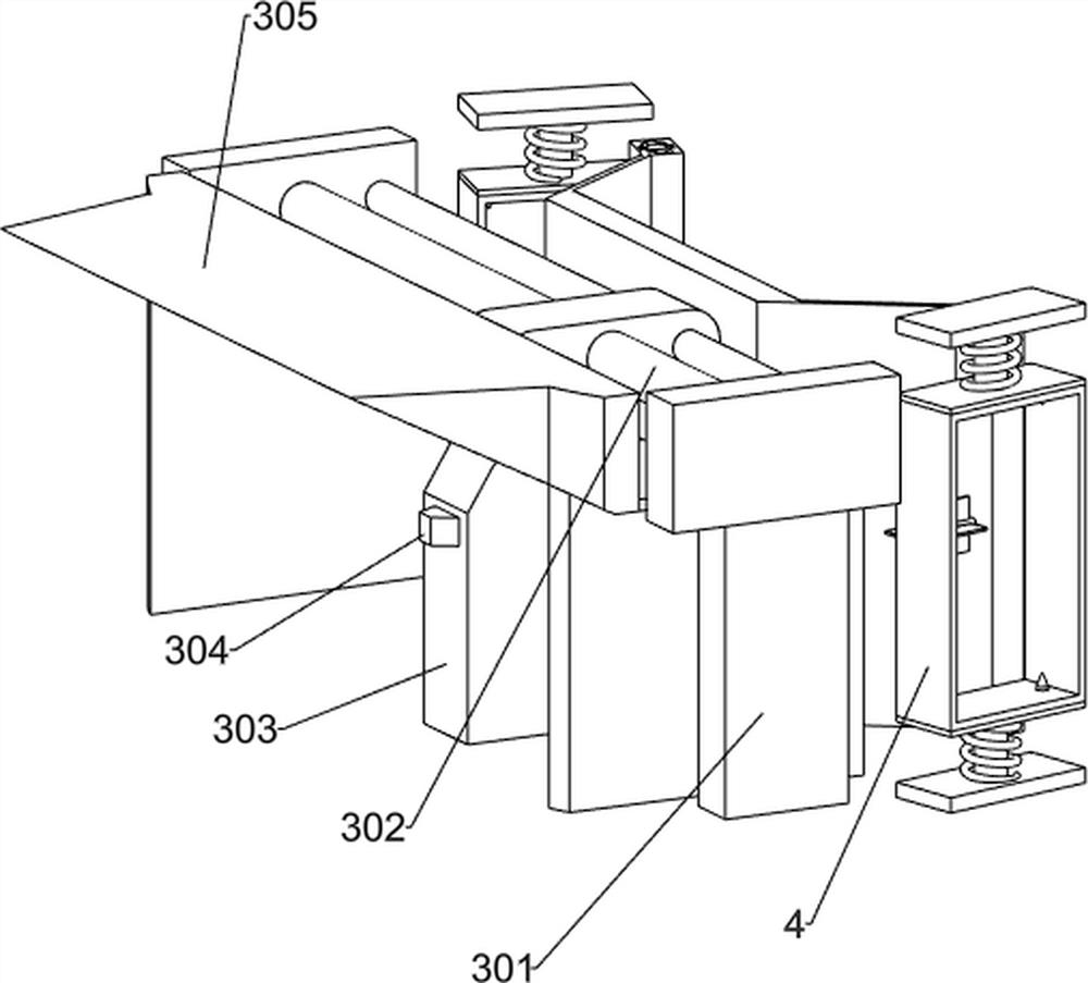
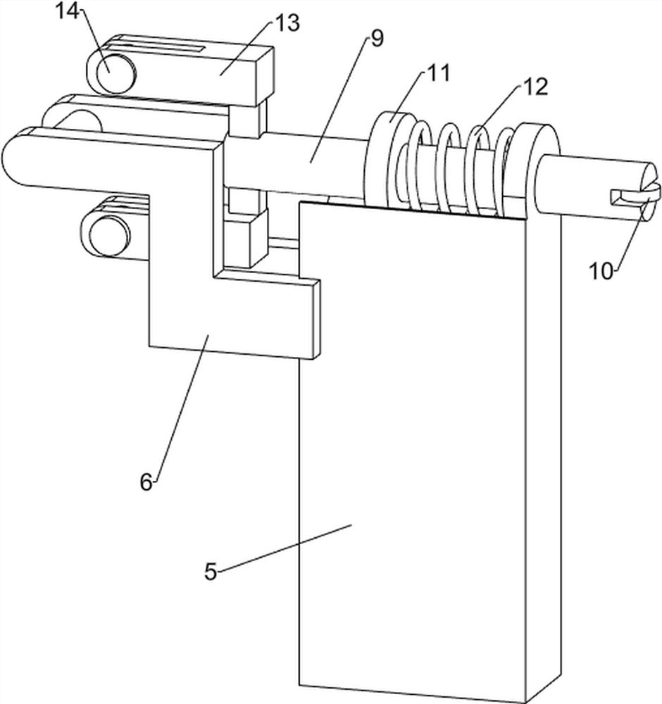
[0041] like Figure 5 , Figure 6 , Figure 7 , Figure 8 , Figure 9 , Figure 10 , Figure 11 and Figure 12 As shown, on the basis of Embodiment 2, it also includes a second supporting plate 5, a first fixing plate 6, a connecting shaft 7, a cutting knife 8, a first connecting rod 9, a runner 10, a fixing ring 11, a second A spring 12, a connecting plate 13 and a second connecting rod 14, the left side of the fish-shaped frame 1 is provided with a second supporting plate 5, and the left side of the second supporting plate 5 is provided with a first fixing plate 6 on both sides , A connecting shaft 7 is arranged between the two first fixing plates 6, a cutting knife 8 is arranged symmetrically on the connecting shaft 7, and a first connecting rod 9 is slidably arranged on the second support plate 5 , the right end of the first connecting rod 9 is rotatably provided with a runner 10, the runner 10 cooperates with the wedge block 304, the first connecting rod 9 is provi...
PUM
 Abstract
Description
Claims
Application Information
 - R&D Engineer
- R&D Manager
- IP Professional
- Industry Leading Data Capabilities
- Powerful AI technology
- Patent DNA Extraction
Browse by: Latest US Patents, China's latest patents, Technical Efficacy Thesaurus, Application Domain, Technology Topic.
© 2024 PatSnap. All rights reserved.Legal|Privacy policy|Modern Slavery Act Transparency Statement|Sitemap