Wallboard welding-free easy-assembly system
An assembly system, welding-free technology, applied in the direction of walls, building components, buildings, etc., can solve the problems that the height of the wall panel and the skeleton cannot be adjusted again, the installation process of the wall panel is cumbersome, and the assembly is not fast enough, and the installation process is simple and convenient. Simple structure and small construction volume
- Summary
- Abstract
- Description
- Claims
- Application Information
AI Technical Summary
Problems solved by technology
Method used
Image
Examples
Embodiment 1
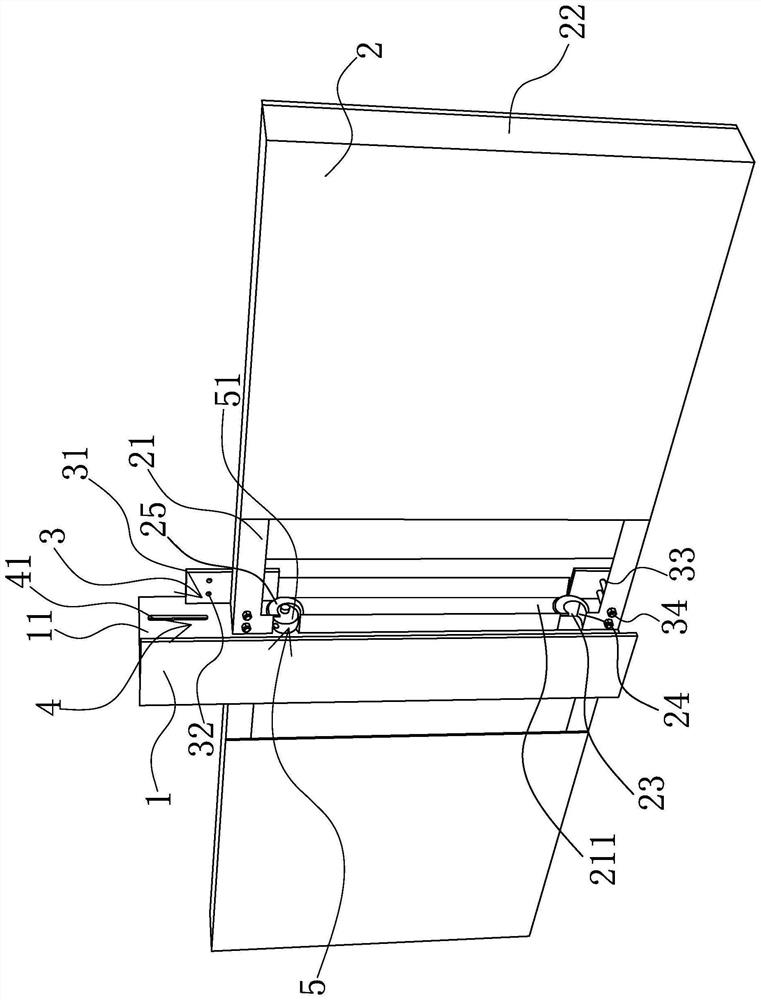
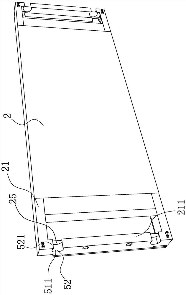
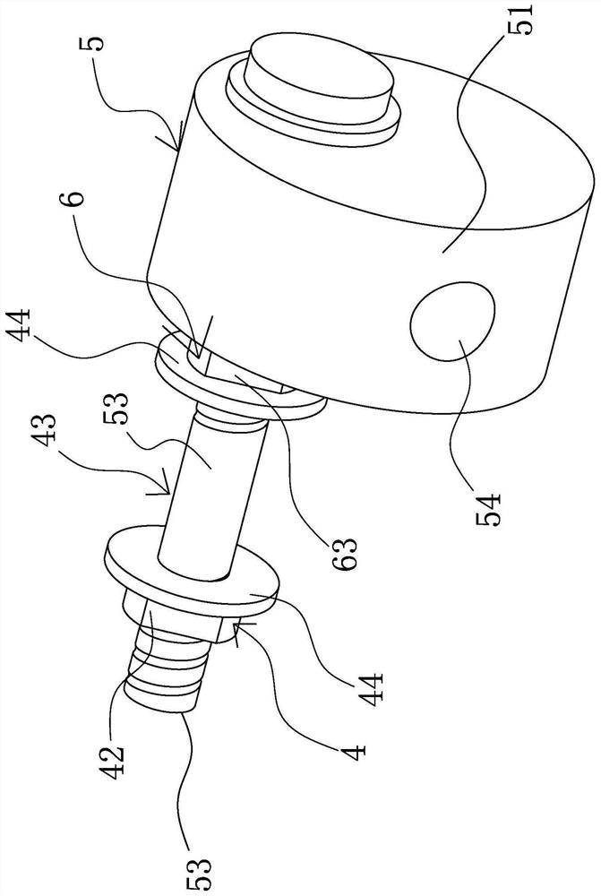
[0037] like Figure 1-5 As shown, the wall panel free of welding and easy assembly system includes a column 1, at least one wall panel 2 is provided on at least one side of the column 1, and an auxiliary positioning structure 3 is provided between the column 1 and the wall panel 2. The adjustable installation structure 4 is provided with an eccentric wheel assembly 5 having at least one eccentric wheel body 51 that is rotated. The side of the wall close to the column 1 has a positioning groove 52 corresponding to the eccentric wheel body 51. The eccentric wheel body 51 is movable. In the positioning groove 52 and when the eccentric wheel body 51 rotates circumferentially by an external force, the circumferential outer side of the eccentric wheel body 51 abuts against the positioning groove 52 so as to clamp the wallboard 2 to the side of the column 1 . Obviously, when the eccentric wheel body 51 here is movably arranged in the positioning groove 52 on one side of the wallboard...
Embodiment 2
[0048] like Figure 6-7 As shown, the structure, principle and implementation steps of this embodiment are similar to those of Embodiment 1, the difference lies in that the first limiting part 63 in this embodiment is a first limiting nut 632 threadedly connected with the eccentric shaft 53, And the first limit nut 632 has a first limit washer 633 sleeved on the outer side of the eccentric wheel shaft 53 on the side close to the eccentric wheel body 51, and the second limit part 64 is a second stop screw threaded with the end of the eccentric wheel shaft 53. Two limit nuts 641, and the second limit nut 641 has a second limit washer 643 sleeved on the outer side of the eccentric wheel shaft 53 in the circumferential direction near the eccentric wheel body 51 .
Embodiment 3
[0050] like Figure 8 As shown, the structure, principle and implementation steps of this embodiment are similar to those of Embodiment 1, the difference lies in that the first limiting portion 63 in this embodiment is integrally formed on the first limiting portion outside the eccentric shaft 53 in the circumferential direction. Block 631, and the first limit block 631 has a first limit gasket 633 sleeved on the outer side of the eccentric wheel shaft 53 on the side close to the eccentric wheel body 51, and the second limit part 64 is threaded with the end of the eccentric wheel shaft 53 The second limiting nut 641 is connected, and the side of the second limiting nut 641 close to the eccentric wheel body 51 has a second limiting washer 643 sleeved on the outer side of the eccentric wheel shaft 53 in the circumferential direction.
PUM
 Abstract
Description
Claims
Application Information
 - R&D
- Intellectual Property
- Life Sciences
- Materials
- Tech Scout
- Unparalleled Data Quality
- Higher Quality Content
- 60% Fewer Hallucinations
Browse by: Latest US Patents, China's latest patents, Technical Efficacy Thesaurus, Application Domain, Technology Topic, Popular Technical Reports.
© 2025 PatSnap. All rights reserved.Legal|Privacy policy|Modern Slavery Act Transparency Statement|Sitemap|About US| Contact US: help@patsnap.com


