A high-efficiency continuous medicine drying device

A technology for drying devices and medicines, which is used in dryers for stationary materials, drying of solid materials, and handling of dry goods, etc., can solve the problems of low dehydration efficiency, high risk, poor dehydration effect, etc., to improve dehydration efficiency and effective adsorption. sexual effect

Active Publication Date: 2022-02-01
北京市永康药业有限公司
View PDF14 Cites 0 Cited by
  • Summary
  • Abstract
  • Description
  • Claims
  • Application Information

AI Technical Summary

Problems solved by technology

[0004] The purpose of the present invention is to solve the defects of relatively high risk, low dehydration efficiency and poor dehydration effect existing in the drying of gaseous medicines, and therefore provides an efficient and continuous medicine drying device

Method used


Image

  • A high-efficiency continuous medicine drying device
  • A high-efficiency continuous medicine drying device

Examples


Embodiment 1

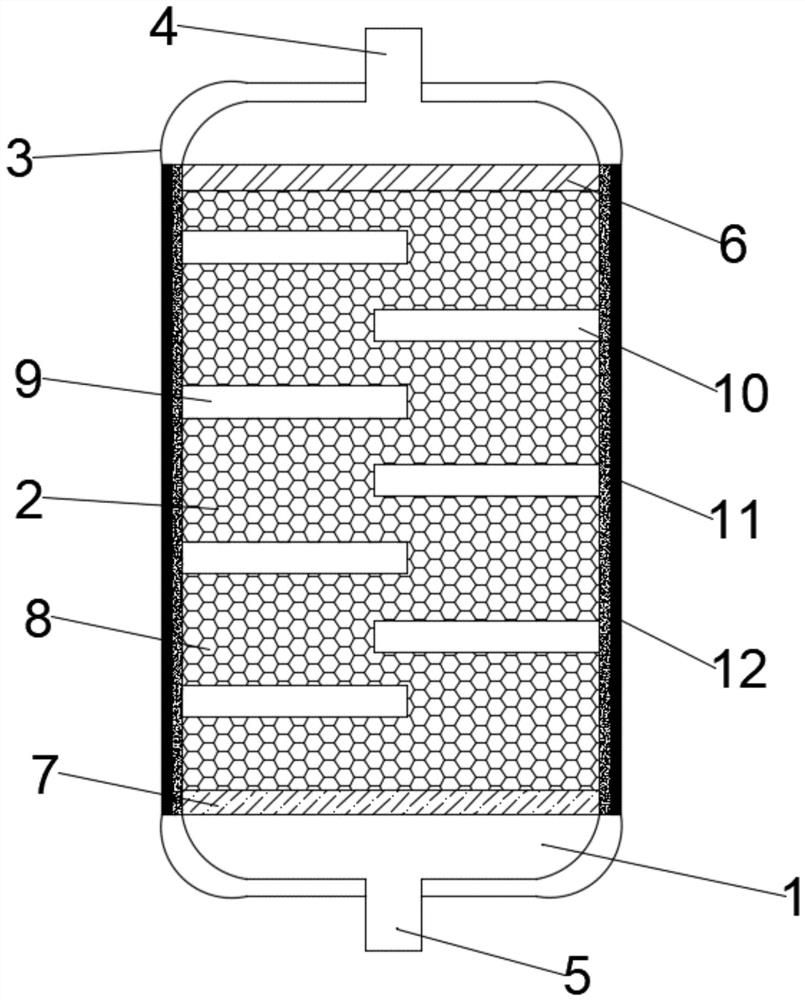
[0032] An efficient and continuous medicine drying device, such as figure 1 As shown, it includes a drying device body 1. The drying device body 1 includes a device cavity 2 and a device housing 3 arranged on the surface of the device cavity 2. The upper port of the device cavity 2 is provided with a discharge port 4. The device cavity A feed port 5 is provided at the lower port of 7. Desiccant 8 is filled between the air guide plate 6 and the diffuser plate 7 .

[0033] Several groups of first baffles 9 and second baffles 10 are arranged between the guide plate 6 and the diffuser plate 7 , the first baffle 9 is arranged on the left side of the inner wall of the device cavity 2 , and the second baffle 10 is arranged at the On the right side of the inner wall of the device cavity 2 , the first baffles 9 and the second baffles 10 are staggered at equal intervals.

[0034] A heating layer 11 and an insulating layer 12 are disposed between the device cavity 2 and the device casi...

Embodiment 2

[0046] An efficient and continuous medicine drying device, such as figure 1 As shown, it includes a drying device body 1. The drying device body 1 includes a device cavity 2 and a device housing 3 arranged on the surface of the device cavity 2. The upper port of the device cavity 2 is provided with a discharge port 4. The device cavity A feed port 5 is provided at the lower port of 7. Desiccant 8 is filled between the air guide plate 6 and the diffuser plate 7 .

[0047] Several groups of first baffles 9 and second baffles 10 are arranged between the guide plate 6 and the diffuser plate 7 , the first baffle 9 is arranged on the left side of the inner wall of the device cavity 2 , and the second baffle 10 is arranged at the On the right side of the inner wall of the device cavity 2 , the first baffles 9 and the second baffles 10 are staggered at equal intervals.

[0048] A heating layer 11 and an insulating layer 12 are disposed between the device cavity 2 and the device casi...

Embodiment 3

[0059] An efficient and continuous medicine drying device, such as figure 1 As shown, it includes a drying device body 1. The drying device body 1 includes a device cavity 2 and a device housing 3 arranged on the surface of the device cavity 2. The upper port of the device cavity 2 is provided with a discharge port 4. The device cavity A feed port 5 is provided at the lower port of 7. Desiccant 8 is filled between the air guide plate 6 and the diffuser plate 7 .

[0060] Several groups of first baffles 9 and second baffles 10 are arranged between the guide plate 6 and the diffuser plate 7 , the first baffle 9 is arranged on the left side of the inner wall of the device cavity 2 , and the second baffle 10 is arranged at the On the right side of the inner wall of the device cavity 2 , the first baffles 9 and the second baffles 10 are staggered at equal intervals.

[0061] A heating layer 11 and an insulating layer 12 are disposed between the device cavity 2 and the device casi...


PUM


Abstract

The invention relates to a high-efficiency and continuous medicine drying device, which comprises a drying device body, the drying device body includes a device cavity and a device shell arranged on the surface of the device cavity, a discharge port is arranged at the upper port of the device cavity, and the device The lower port of the cavity is provided with a feed port, the inside of the device cavity is provided with a deflector on the side close to the discharge port, and the side of the device cavity close to the feed port is provided with a diffuser, a deflector and A desiccant is filled between the diffuser plates. The present invention prepares a kind of medicine drying equipment, which can have a good drying effect on gas or volatile medicines, and overcomes the relatively high risk, low dehydration efficiency and poor dehydration effect existing in the drying of gas medicines. Defects. The diffuser plate, deflector plate and desiccant provided in the present invention all contribute to the drying of the gas, and the purpose of the heating layer and the thermal insulation layer is to provide a suitable drying environment for the drying device.

Description

technical field [0001] The invention relates to the field of medicine production equipment, in particular to an efficient and continuous medicine drying device. Background technique [0002] In the production of medicines, in order to ensure the uniformity and good fluidity of medicines, the raw materials are often made into solid particles (pills, capsules, and moments) by a certain method, and the thermal and non-thermal effects of microwaves are used to increase the internal temperature of the medicine. , generate pressure, accelerate the transfer of confined water molecules, and gradually evaporate the water in the processed items to the outside. At this time, appropriate hot air is passed through the drying equipment to take away the evaporated water, thereby completing the drying of the medicine. [0003] The above is more effective for drying solid chemicals, but it is more difficult to dry gas or volatile chemicals, especially some corrosive chemicals. At present, m...

Claims


Application Information

Patent Timeline
Patent Type & Authority Patents(China)
IPC IPC(8): F26B5/16F26B9/06F26B25/00F26B25/04
CPCF26B5/16F26B9/06F26B25/002F26B25/04
Inventor 孙一森秦红燕
Owner 北京市永康药业有限公司
Why Eureka
Try Eureka