Improved switch

An improved switching technology, which is applied in the direction of electric switches, contacts, electrical components, etc., can solve the problems of inconvenient installation, disassembly and maintenance, poor sealing of switches, and large influence, so as to achieve convenient connection, high safety and convenience The effect of maintenance operations

Pending Publication Date: 2021-09-17
安徽锡恩电气科技有限责任公司
View PDF0 Cites 0 Cited by
  • Summary
  • Abstract
  • Description
  • Claims
  • Application Information

AI Technical Summary

Problems solved by technology

[0006] An improved switch proposed by the present invention solves the problem of poor sealing of the existing switch, inconvenient installation, disassembly and maintenance, and great influence

Method used


Image

  • Improved switch
  • Improved switch
  • Improved switch

Examples


Embodiment 1

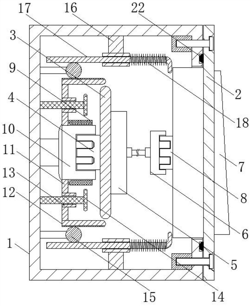
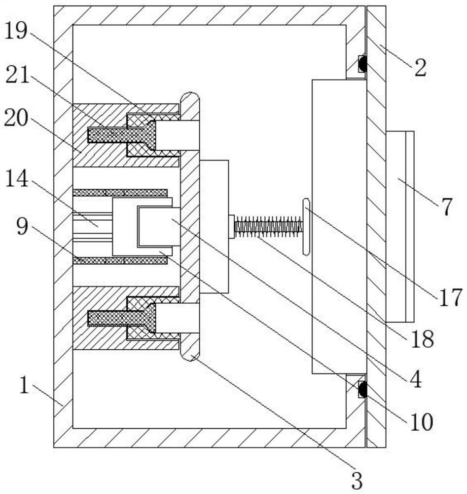
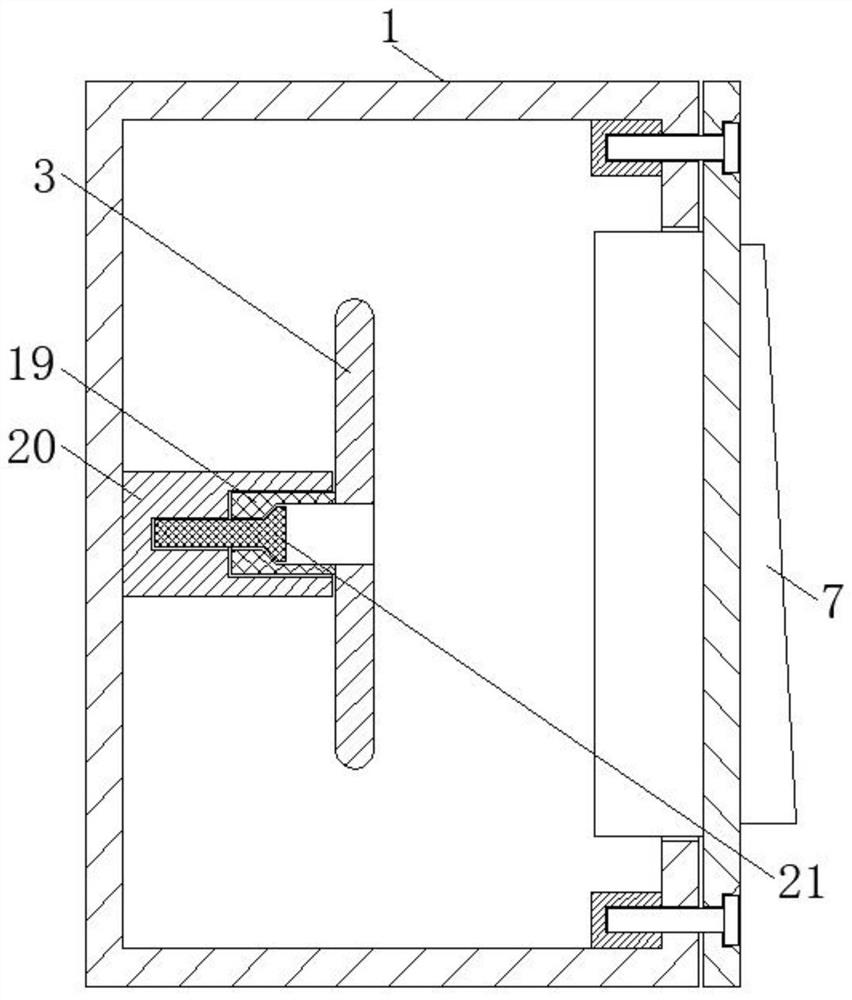
[0029] refer to Figure 1-4 As shown, an improved switch includes a junction box 1, a panel 2, and a mounting plate 3. The front and rear sides of the mounting plate 3 are respectively equipped with a first slot 4 and a wiring panel 5, and the wiring panel 5 is connected to a second A connector 6, a switch 7 is arranged in the panel 2, and a second slot 8 is installed on the rear side of the panel 2, a sliding frame 9 is fixedly connected to the center of the rear inner wall of the junction box 1, and a sliding frame 9 is slidably arranged in the sliding frame 9. The second connecting head 10, the upper and lower ends of the second connecting head 10 are fixedly connected with the connecting plate 11, and the ends of the upper and lower connecting plates 11 are fixedly connected with the first rack 12. A mounting mechanism is provided between the upper and lower inner walls of the bar 12 and the junction box 1, and a mounting mechanism is provided between the left and right en...

Embodiment 2

[0031] refer to Figure 1-4As shown, in the case that other parts are the same as those in Embodiment 1, the difference between this embodiment and Embodiment 1 is that the panel 2 is fixedly connected to the outer edge of the front side of the junction box 1 through bolts, and the rear side of the panel 2 is fixedly installed There is a square rubber pad 22, and the square rubber pad 22 fits and seals with the outer edge of the front side of the junction box 1, and a vertical plate is fixedly connected between the left and right sides of the rear end of the sliding frame 9 and the rear inner wall of the junction box 1 , the rear side of the second connecting head 10 extends on the rear side of the sliding frame 9, and the connecting plate 11 is fixedly connected to the upper and lower sides of the rear extension end respectively, and the first racks 12 on the upper and lower sides are respectively arranged on The gears 15 on the upper and lower sides are close to each other, ...


PUM


Abstract

The invention discloses an improved switch, relates to the field of switches, and aims to solve the problems that an existing switch is poor in sealing performance, inconvenient to mount, dismount and maintain and large in influence, the improved switch comprises a junction box, a panel and a mounting plate, wherein the front side and the rear side of the mounting plate are provided with a first slot and a wiring panel respectively; a first connector is connected to the wiring panel, a switch is arranged in the panel, a second slot is formed in the rear side face of the panel, a second connector is arranged in the sliding frame, the two ends of the second connector are fixedly connected with connecting plates, one end of each connecting plate is fixedly connected with a first rack. Mounting mechanisms are arranged between the first racks and the upper and lower inner walls of the junction box, and mounting mechanisms are arranged between the left and right ends of the mounting plate and the inner wall of the rear side of the junction box. The improved switch can be conveniently mounted and dismounted, can be flexibly powered off, is high in safety, is convenient to maintain, and does not affect the use of other electric appliances.

Description

technical field [0001] The invention relates to the field of switches, in particular to an improved switch. Background technique [0002] A switch is an electronic component that can open a circuit, interrupt the current flow, or allow it to flow to other circuits. The most common switches are human-operated electromechanical devices that have one or more electrical contacts. The "closed" of the contact means that the electronic contact is conducting and allows the current to flow; the "open" of the switch means that the electronic contact is not conducting and forms an open circuit, and the current is not allowed to flow. [0003] The simplest switch has two metals that are called " contacts ", and electric current is formed circuit when two contacts contact, and electric current opens circuit when two contacts do not contact. When selecting the contact metal, it is necessary to consider its corrosion resistance, because most metals will form insulating oxides after oxida...

Claims


Application Information

Patent Timeline
Patent Type & Authority Applications(China)
IPC IPC(8): H01H9/02H01H9/04H01H1/58
CPCH01H9/02H01H9/04H01H1/5866
Inventor 童新
Owner 安徽锡恩电气科技有限责任公司
Why Eureka
Try Eureka