Cooling unit for an electrical machine and method for producing cooling unit

A technology for cooling units, machines, applied in electrical components, cooling/ventilation devices, manufacturing of motor generators, etc., can solve the problems of increased temperature, increased electrical machine packaging, i.e. outer size, less heat and material transport, etc., achieve the effect of avoiding repetition

Pending Publication Date: 2021-09-17
SEG AUTOMOTIVE GERMANY GMBH
View PDF2 Cites 0 Cited by
  • Summary
  • Abstract
  • Description
  • Claims
  • Application Information

AI Technical Summary

Problems solved by technology

This creates so-called dead zones in other areas with low flow rates and low heat and mass transport, which leads to temperature increases
Although this problem can be solved by guide vanes or the inflow portion in the middle of the radial direction (that is, the inlet arranged in the middle), the manufacture of the guide vanes is complicated, and the radial inflow increases the packaging of the electric machine, that is, the outer size

Method used


Image

  • Cooling unit for an electrical machine and method for producing cooling unit
  • Cooling unit for an electrical machine and method for producing cooling unit
  • Cooling unit for an electrical machine and method for producing cooling unit

Examples


Embodiment Construction

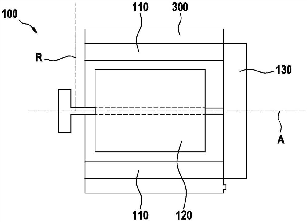
[0029] figure 1An electric machine 100 according to the invention with a cooling unit 300 is schematically shown in a preferred embodiment. The electric machine 100 has a stator 110 and a rotor 120 arranged inside the stator 110 , which is rotatable about an axis of rotation A, which also defines the axial direction. Let R correspond to the radial direction.

[0030] Furthermore, a control and regulation unit 130 is arranged, which has in particular a so-called inverter.

[0031] Cooling unit 300 has an at least substantially hollow-cylindrical jacket, or is designed substantially jacket-shaped, and is arranged around stator 110 . For a more detailed design of the cooling unit, see the subsequent drawings and related descriptions.

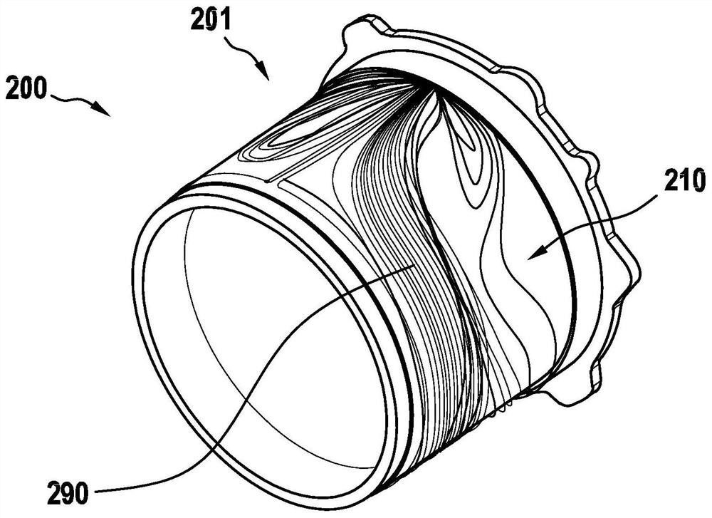
[0032] figure 2 A cooling unit 200 not according to the invention is shown in perspective view in FIG. The cooling unit 200 has a substantially hollow cylindrical envelope 201 , at least part of which is shown. Cooling channels 210 are provi...


PUM


Abstract

The invention relates to a cooling unit (300) for an electrical machine, an electrical mechaine and a method for producing the cooling unit. The cooling unit comprises an at least substantially hollow cylindrical jacket (301), a cooling channel (310) formed in the jacket, and an inlet (302) and an outlet (303) for a coolant; the cooling channel extends in the circumferential direction (U) of the jacket, the width (B) of the cooling channel is equal to the majority of the axial length of the jacket (301), the inlet and the outlet are connected via the cooling channel (310) and are each arranged at an axial end of the jacket (301), the cooling channel (310) has a groove-shaped inlet region (320) adjoining the inlet (302), the inlet region (320) extends from the inlet (302) in the axial direction of the jacket along the width (B) of the cooling channel, and the cooling channel (310) has a throttle region (330) which adjoins the inlet region (320) when viewed in the circumferential direction (U) of the jacket, and in the throttle region, the channel height of the cooling channel is smaller in the radial direction of the jacket than in the inlet region (320).

Description

technical field [0001] The invention relates to a cooling unit for an electrical machine, an electrical machine with such a cooling unit, and a method for producing such a cooling unit. Background technique [0002] In electric machines which can operate as motors and / or generators, power losses are dissipated in the form of heat due to energy conversion processes. Thus in highly utilized machines, effective heat dissipation or cooling is beneficial. For this purpose, cooling with a fluid, such as water, as coolant on the stator of the electric machine, in particular so-called jacket cooling or water jacket cooling, is preferably suitable. [0003] Such jacket cooling or corresponding cooling channels can be designed, for example, helically or meander-shaped. From DE 10 2011 076 529 A1 and DE 10 2018 200 365 A1, for example, sheath cooling is known, wherein the cooling channel surrounds the sheath or in the sheath substantially in the form of a helix or helically between t...

Claims


Application Information

Patent Timeline
Patent Type & Authority Applications(China)
IPC IPC(8): H02K9/19H02K5/20H02K15/00H02K15/14
CPCH02K9/19H02K5/20H02K15/00H02K15/14H02K5/203H02K2213/03H02K9/197
Inventor 乔纳斯·亨斯
Owner SEG AUTOMOTIVE GERMANY GMBH
Why Eureka
Try Eureka