Three-dimensional optical coherence elastography detection device applied to retina operation

A three-dimensional optical and elastic imaging technology, which is applied in the fields of application, medical science, and eye testing equipment, etc., can solve the problems of excessive dust residue, limited observation ability, troublesome cleaning, etc.

Inactive Publication Date: 2021-09-21
黄国富
View PDF0 Cites 0 Cited by
  • Summary
  • Abstract
  • Description
  • Claims
  • Application Information

AI Technical Summary

Problems solved by technology

[0004] In order to overcome the disadvantages that it is difficult to detect the problem due to people's limited observation ability, and the image is easy to leave too much dust after detection in pieces, and it is very troublesome to clean up. Three-dimensional optical coherence elastography detection device applied to retinal surgery for cleaning images into slices

Method used


Image

  • Three-dimensional optical coherence elastography detection device applied to retina operation
  • Three-dimensional optical coherence elastography detection device applied to retina operation
  • Three-dimensional optical coherence elastography detection device applied to retina operation

Examples


Embodiment 1

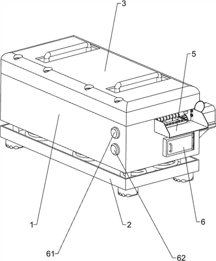
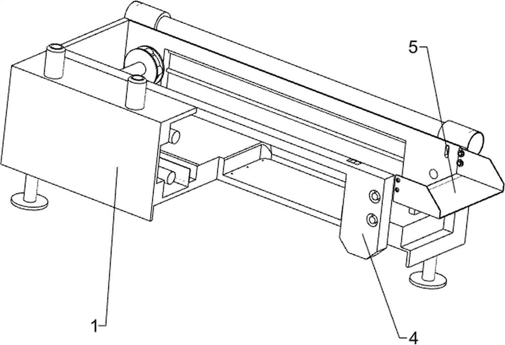
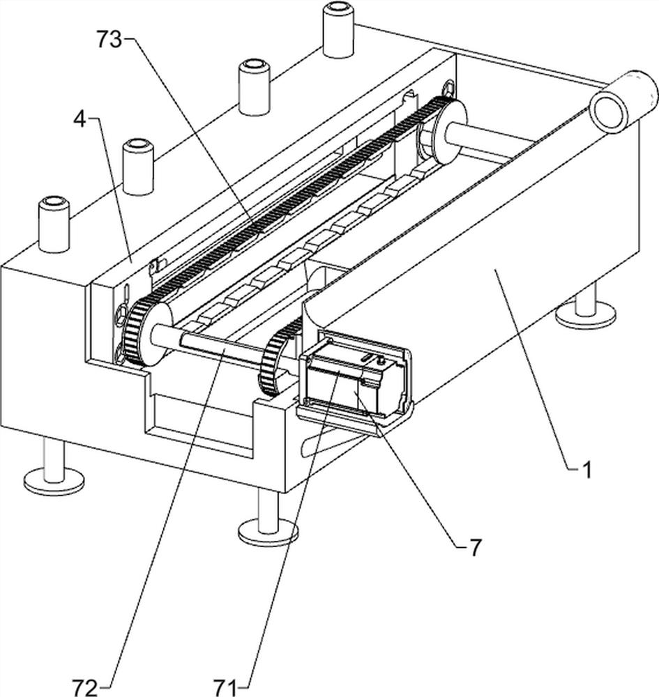
[0036] A three-dimensional optical coherence elastography detection device applied to retinal surgery, such as Figure 1-Figure 5 As shown, it includes a light-shielding bottom box 1, a support base 2, a sealing cover plate 3, a partition plate 4, a load-bearing plate 5, a start button 61, a stop button 62, a driving mechanism 7 and a detection mechanism 8, and the bottom of the light-shielding bottom box 1 is fixed. Connected with a supporting base 2, the upper right side of the light-shielding bottom box 1 is hingedly provided with a sealing cover 3, the left part of the light-shielding bottom box 1 is provided with a partition plate 4, and the upper right side of the front part of the light-shielding bottom box 1 is provided with a load-bearing plate 5, A start button 61 is provided on the upper part of the front left side outside the light-shielding bottom box 1, a stop button 62 is provided on the lower front side outside the left side of the light-shielding bottom box 1, ...

Embodiment 2

[0041] On the basis of Example 1, such as Figure 6-Figure 12 As shown, a support mechanism 9 is also included, and the support mechanism 9 includes a movable bottom block 91, a reset guide column 92, a buffer column 93, a pressure sensor 94, a support chassis 95, a support frame 96, a lifting solenoid valve 97, and a top frame Block 98, lifting block 99, transmission engagement lever 910, connecting side block 911, support spring column 912, spacer block 913 and top position cross bar 914, shading bottom box 1 left side is provided with reset guide post 92 up and down symmetrically, two up and down A movable bottom block 91 is slidingly arranged between the side reset guide pillars 92, a buffer column 93 is provided on the left front side of the light-shielding bottom box 1, a pressure sensor 94 is provided in the middle of the buffer column 93, and a lift is provided on the lower side of the right part of the mobile bottom block 91. Solenoid valve 97, lift solenoid valve 97 ...

Embodiment 3

[0046] On the basis of embodiment 1 and embodiment 2, such as Figure 13 and Figure 14 As shown, also includes a shading reset mechanism 11, the shading reset mechanism 11 includes a shading cover 111, a light shielding plate 112, a guide rod 113, an electromagnetic block 114 and a travel switch 115, and a shading cover 111 is provided at the rear part of the inner surface of the sealing cover plate 3 , the front portion of the sunshade 111 is symmetrically provided with guide rods 113, and the guide rods 113 on the left and right sides are slidingly provided with a light shield 112, and the inner front of the sunshade 111 is provided with an electromagnetic block 114, and the electromagnetic block 114 cooperates with the light shield 112 , The front portion of the dividing plate 4 is provided with a travel switch 115 .

[0047] Also include dust removal mechanism 12, dust removal mechanism 12 includes dust removal sponge rod 121, positioning cross bar 122 and pressing down ...


PUM


Abstract

The invention relates to a detection device, in particular to a three-dimensional optical coherence elastography detection device applied to a retina operation. The three-dimensional optical coherence elastography detection device applied to the retina operation, which is convenient for people to detect coherence elastography and can clean an image slice, needs to be designed. The three-dimensional optical coherence elastography detection device applied to the retina operation comprises a shading bottom box, wherein a supporting base is arranged on one side of the shading bottom box; a sealing cover plate which is mounted on the shading bottom box in a hinged manner; and a partition plate which is mounted on the shading bottom box. Through cooperation of the driving mechanism and the detection mechanism, the image slice moves backwards by a certain distance to block a light propagation path of the first photoelectric sensor, the first photoelectric sensor sends a signal, and the control module transmits detection data after receiving the signal, so that people can conveniently detect coherent elastography.

Description

technical field [0001] The invention relates to a detection device, in particular to a three-dimensional optical coherent elastic imaging detection device applied to retinal surgery. Background technique [0002] Elastography is a technology that takes elastic parameters such as Young's modulus, shear modulus, stress and strain of soft tissue as the imaging object. At present, after coherent elastography after retinal surgery, the whole piece will be inspected. Most people place the pieced image under the light for visual inspection. Due to people's limited observation ability, it is difficult to detect the problem, and the image piece Too much dust is easy to remain after the detection, and cleaning is very troublesome. [0003] Therefore, it is necessary to design a three-dimensional optical coherent elastography detection device for retinal surgery that is convenient for people to detect coherent elastography, and can clean up images in sheets, as well as solve the exist...

Claims


Application Information

Patent Timeline
Patent Type & Authority Applications(China)
IPC IPC(8): A61B3/10
CPCA61B3/102
Inventor 黄国富赵雁之
Owner 黄国富
Why Eureka
Try Eureka