Discharge separation and concentrated transportation device of punching machine

A technology of stamping machine tools and separation sets, applied in the direction of stripping devices, feeding devices, positioning devices, etc., can solve the problems of multiple workers, low efficiency, and inability to improve machine tools, and achieve the effect of automation

Pending Publication Date: 2021-09-21
青岛瑞利杰金属有限公司
View PDF11 Cites 0 Cited by
  • Summary
  • Abstract
  • Description
  • Claims
  • Application Information

AI Technical Summary

Problems solved by technology

The efficiency of such a processing process is very low. As a part of the production line, the stamping machine tool still needs to be processed downstream to wait for the stamping parts. The processes of wiping and cleaning, stamping parts sorting, and stamping machine handling often cannot keep up with the production rhythm of the stamping machine. And after counting the two workers in the feeding process, the entire stamping machine needs at least six workers to ensure normal production, which is a luxury in the current situation of difficult recruitment
However, the transformation of the stamping machine tool itself exceeds the technical strength of general metal processing and manufacturing enterprises, so it is impossible to improve the machine tool itself
[0004] Therefore, there is currently a need for a solution that can solve two problems. The first is to solve the maintenance problem after the stamping machine is finished, that is, the problem of cleaning grease and storing it for transfer; the second is to solve the problem that the normal production of the stamping machine requires more workers. problem, reducing the number of workers required

Method used


Image

  • Discharge separation and concentrated transportation device of punching machine
  • Discharge separation and concentrated transportation device of punching machine
  • Discharge separation and concentrated transportation device of punching machine

Examples


Embodiment 1

[0036] The purpose of this embodiment is to provide a solution for unloading or unloading with a certain degree of automation, which replaces the only operating table / table used to clean the punching machine.

[0037] The usage method of this embodiment is as follows:

[0038] 1. According to the size of the finished stamping part, start the power mechanism 5 in advance to adjust the height of the telescopic mechanism 6 to ensure that it can hold the stamping part;

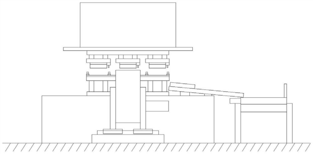
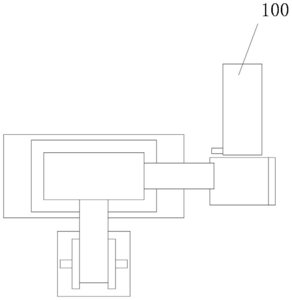
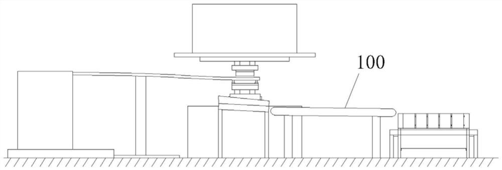
[0039] 2. After the stamping parts are processed, the feeding mechanism of the stamping machine itself transports the processed stamping parts to the slide table 100, and the stamping parts fall under the action of gravity;

[0040] 3. The worker feeds the stamped parts that have fallen from the sliding table 100 into the through hole 4 of the first base 3 of the cleaning module 1, and starts the telescopic mechanism 6, which stretches out to clamp the stamped parts;

[0041] 4. Start the sliding mechanism 10 of ...

Embodiment 2

[0057] This embodiment is made on the basis of the first embodiment, on which a water spray mechanism is added to spray liquid that can play a cleaning role toward the stamping parts before the wiping plate 9 is cleaned, assisting in cleaning work.

[0058] The water guide bar 12 is similar to common industrial wind knives, and is in the shape of a column. A notch 16 is provided on the side of the wiping plate 9 facing the through hole 4 or toward the side of the clamping assembly, exposing the bracket plate 8 . Fix the water guide strip 12 on the bracket plate 8, ensure that the water guide strip 12 is closer to the stamping part than the wiping plate 9, and spray the liquid on the stamping part first. A water channel 16 is provided in the water guide bar 12, and the water channel 16 is arranged along its length direction. The water outlet hole 14 on the side wall of the water guide bar 12 is connected to the water channel, and the water injection interface 13 is arranged on ...


PUM


Abstract

The invention relates to a discharge separation and concentrated transportation device of a punching machine,which comprises a cleaning module and a storage module, the cleaning module comprises a first base and independent task units, the first base is provided with a plurality of long-strip-shaped through holes, each through hole is correspondingly provided with one independent task unit, and each independent task unit is divided into a clamping assembly and a wiping assembly; each clamping assembly comprises power mechanisms and telescopic mechanisms, the front wall and the rear wall in the through hole are each provided with one power mechanism, each power mechanism is provided with one telescopic mechanism, and the telescopic mechanisms are driven by the power mechanisms to do lifting motion in the through holes; the wiping assembly comprises outer box bodies, a support plate, a wiping plate and sliding mechanisms, each through hole corresponds to one outer box body, the sliding mechanisms are arranged in the length direction of the through holes, each outer box body is provided with two sliding mechanisms, and the wiping plate covers the inner wall of the support plate; and the storage module comprises a storage box body which is arranged below the first base.

Description

technical field [0001] The invention relates to a machine tool matching equipment, in particular to a machine tool discharge separation and collection device. Background technique [0002] The production operation process of the stamping machine tool is as follows: start the machine tool feeding device, and the material roll is fed into the punch of the machine tool; after the punch is processed into the expected shape, the processed stamping parts are transported from the punch to the discharge slide through the conveying mechanism; Stamping parts slide from the discharge slide to the storage table, manually check whether there is grease on the outer surface, and try to clean the grease; after cleaning, put the stamping parts on the conveyor belt, and set the packaging table at the end of the conveyor belt. When the stamping parts arrive After packing the countertops, the worker lays a soft anti-scratch cloth on the bottom of the stamping parts to protect the stamping parts...

Claims


Application Information

Patent Timeline
Patent Type & Authority Applications(China)
IPC IPC(8): B21D22/02B21D43/20B21D45/06B08B1/00B08B3/02
CPCB21D22/02B21D43/20B21D45/06B08B1/006B08B3/02
Inventor 李辉
Owner 青岛瑞利杰金属有限公司
Why Eureka
Try Eureka