

A Biomass In-Situ Controlled Nitrogen Gasification Cogeneration Thermal Charcoal Device
A biomass and in-situ technology, applied in the gasification process, the manufacture of combustible gas, and the petroleum industry, can solve the problems of high process energy consumption, complex process flow, and low energy efficiency of the system, so as to avoid ammonia escape and improve energy utilization. Effect of improving and reducing NOx emission
- Summary
- Abstract
- Description
- Claims
- Application Information
AI Technical Summary
Problems solved by technology
Method used
Image

Examples
Embodiment 1
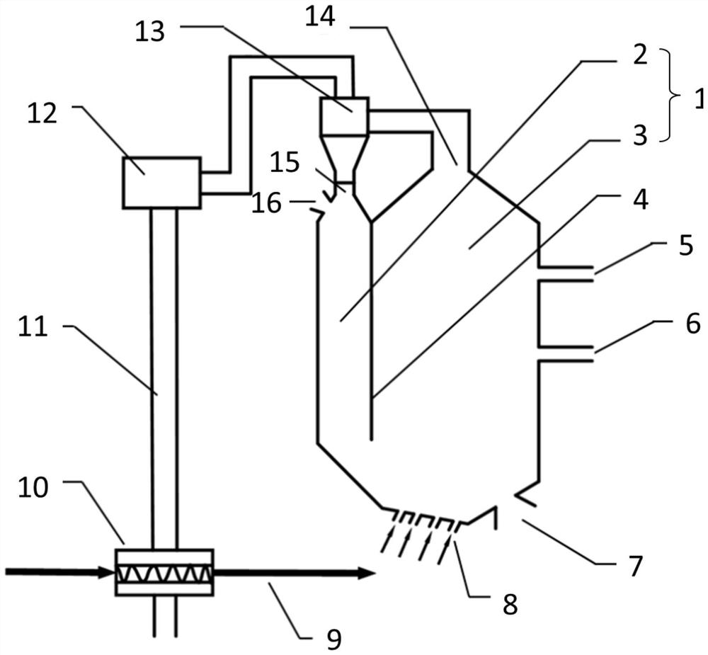
[0047] This embodiment provides a biomass in-situ nitrogen-controlled gasification co-generation thermal carbon device, such as figure 1 As shown, the device includes a coupling furnace 1, the coupling furnace 1 is divided into a pyrolysis zone 2 and a gasification combustion zone 3 by a heat exchange plate 4, the heat exchange plate 4 extends from the top of the coupling furnace 1 to Middle and lower part; the corresponding first furnace bottom plate below the pyrolysis zone 2 slopes downward from the outside to the inside, and the second furnace bottom plate below the gasification combustion zone 3 and close to the pyrolysis zone 2 slopes downward from the outside to the inside, so The third furnace bottom plate below the gasification combustion zone 3 and away from the pyrolysis zone 2 is inclined upward from the inside to the outside, and an air distribution plate 8 is provided on the second furnace bottom plate, and coke is provided on the third furnace bottom plate. A co...
Embodiment 2
[0060] This embodiment provides a biomass in-situ nitrogen-controlled gasification co-generation thermal carbon device, such as figure 1 As shown, the device includes a coupling furnace 1, the coupling furnace 1 is divided into a pyrolysis zone 2 and a gasification combustion zone 3 by a heat exchange plate 4, the heat exchange plate 4 extends from the top of the coupling furnace 1 to Middle and lower part; the corresponding first furnace bottom plate below the pyrolysis zone 2 slopes downward from the outside to the inside, and the second furnace bottom plate below the gasification combustion zone 3 and close to the pyrolysis zone 2 slopes downward from the outside to the inside, so The third furnace bottom plate below the gasification combustion zone 3 and away from the pyrolysis zone 2 is inclined upward from the inside to the outside, and an air distribution plate 8 is provided on the second furnace bottom plate, and coke is provided on the third furnace bottom plate. A co...
Embodiment 3
[0065] This embodiment provides a biomass in-situ nitrogen-controlled gasification co-generation thermal carbon device, such as figure 1 As shown, the device includes a coupling furnace 1, the coupling furnace 1 is divided into a pyrolysis zone 2 and a gasification combustion zone 3 by a heat exchange plate 4, the heat exchange plate 4 extends from the top of the coupling furnace 1 to Middle and lower part; the corresponding first furnace bottom plate below the pyrolysis zone 2 slopes downward from the outside to the inside, and the second furnace bottom plate below the gasification combustion zone 3 and close to the pyrolysis zone 2 slopes downward from the outside to the inside, so The third furnace bottom plate below the gasification combustion zone 3 and away from the pyrolysis zone 2 is inclined upward from the inside to the outside, and an air distribution plate 8 is provided on the second furnace bottom plate, and coke is provided on the third furnace bottom plate. A co...
PUM
| Property | Measurement | Unit |
|---|---|---|
| angle | aaaaa | aaaaa |
| angle | aaaaa | aaaaa |
| angle | aaaaa | aaaaa |
Abstract
Description
Claims
Application Information