Slope support construction method combined with building main body structure

A technology that combines the main body of the building and the structure. It is applied in infrastructure engineering, architecture, underwater structures, etc. It can solve the problems of affecting the external landscape of the project, high vertical support height, and high safety risks, reducing the amount of earthwork backfill, The effect of saving project cost and reducing risk

Inactive Publication Date: 2021-09-21
广东佰业泰建设工程有限公司
View PDF3 Cites 0 Cited by
  • Summary
  • Abstract
  • Description
  • Claims
  • Application Information

AI Technical Summary

Problems solved by technology

If a conventional vertical retaining wall is used for support, the vertical support height is too high, the overall safety risk is high, and the cost is huge, and the full vertical retaining wall affects the external landscape of the project

Method used


Image

  • Slope support construction method combined with building main body structure

Examples


Embodiment 1

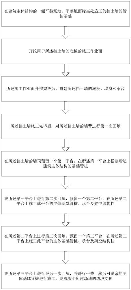
[0041] A slope support construction method combined with the main structure of the building, comprising the following steps:

[0042] S1. Level the site on one side of the main structure of the building, and level the pipe pile foundation of the retaining wall constructed at the ground level.

[0043] That is to say, when the site that needs to be constructed is uneven, the ground of the site should be leveled first on the slope side of the site, and a one-way plastic geogrid should be laid on the ground at the same time. Because it is located on one side of the slope, an L-shaped buttress-type retaining wall is adopted, and the support form of backfill graded slope is adopted to complete the pipe pile extrusion of the retaining wall.

[0044] S2. Excavating the construction work surface for the base plate of the retaining wall.

[0045] That is to say, the construction work surface is excavated, and the buttress type retaining wall is placed on the construction work surface....

Embodiment 2

[0060] A slope support construction method combined with the main structure of the building, comprising the following steps:

[0061] S1. Level the site on one side of the main structure of the building, and level the pipe pile foundation of the retaining wall constructed at the ground level.

[0062] That is to say, when the site that needs to be constructed is uneven, the ground of the site should be leveled first on the slope side of the site, and a one-way plastic geogrid should be laid on the ground at the same time. Because it is located on one side of the slope, an L-shaped buttress-type retaining wall is adopted, and the support form of backfill graded slope is adopted to complete the pipe pile extrusion of the retaining wall.

[0063] S2. Excavating the construction work surface for the base plate of the retaining wall.

[0064] That is to say, the construction work surface is excavated, and the buttress type retaining wall is placed on the construction work surface....


PUM


Abstract

The invention provides a slope support construction method combined with a building main body structure. The method comprises the following steps of leveling a site, excavating a construction working surface of a bottom plate of a retaining wall, building the bottom plate, a wall body and a bearing platform of the retaining wall, carrying out primary backfilling, reserving a first platform on the wall top of the retaining wall, building a foundation pipe pile of a building main body structure, performing secondary backfilling, reserving a second platform, constructing a main body foundation pipe pile, a bearing platform and an overhead structure column of the platform, performing third backfilling, reserving a third platform, constructing a main body foundation pipe pile, a bearing platform and an overhead structure column of the platform, performing final backfilling, flattening, constructing main body foundation pipe piles and finishing slope support. By flexibly adopting a combined form of vertical support and step-slope support with different heights, the building main body structure is overhead for graded step-slope, so that the aims of reducing the vertical support height, reducing the risk of an ultrahigh retaining wall, reducing the earthwork backfilling amount and saving the construction cost are fulfilled.

Description

technical field [0001] The invention relates to the technical field of slope support, in particular to a construction method for slope support combined with a building main structure. Background technique [0002] With the development of society, most of the buildings are high-rise residential buildings and villas, which are built on mountainous terrain with large undulations. During the construction process, it is often necessary to support the engineering slope. In actual engineering, for different Depending on the terrain and geological conditions, different forms of slope support are required. [0003] At present, some buildings are built in hilly areas, and the landform units of the site are usually denuded hills and intermountain depressions. The site is uneven, and the trees and vegetation on the mountain are well developed. If a conventional vertical retaining wall is used for support, the height of the vertical support is too high, the overall safety risk is high,...

Claims


Application Information

Patent Timeline
Patent Type & Authority Applications(China)
IPC IPC(8): E02D17/20E02D29/02E02D27/14
CPCE02D17/20E02D29/02E02D27/14
Inventor 黄子容张翔鸿吴林茂许云康刘帅柯少念
Owner 广东佰业泰建设工程有限公司
Why Eureka
Try Eureka