
Cable connection crimping machine and crimping method

A cable splicing and crimping machine technology, applied in the direction of circuits, connections, electrical components, etc., can solve the problems of cable damage at the splicing part, increase splicing resistance, cable depression, etc., to improve accuracy and stability, reduce sticking effect

Pending Publication Date: 2021-09-21
华容县星星营销传媒中心
View PDF0 Cites 3 Cited by
  • Summary
  • Abstract
  • Description
  • Claims
  • Application Information

AI Technical Summary

Problems solved by technology

[0003] When the current crimping machine is working on the splicing of cables, due to the large body size, it is inconvenient to transport and carry, so that the cables that need to be crimped are frequently transported back and forth in the crimping machine, which increases the work flow of the crimping machine and The cable connection is inconvenient; the crimping machine generally uses a hydraulic cylinder as the main output force to perform the crimping work, but the common cylinder body is large, and the cost of use is high, and maintenance is inconvenient. The excessive pressure will cause heavy dents in the connected cables, often causing damage to the interior of the cables at the connected parts, which will affect the quality of the connection, increase the connection resistance, and shorten the service life of the connected cables; the cables have different appearances. diameter and material, when crimping different types of cables, the operator needs to frequently replace the crimping die, which increases the difficulty of the operator's work and greatly reduces the work efficiency of cable connection

Method used


Image

  • Cable connection crimping machine and crimping method
  • Cable connection crimping machine and crimping method
  • Cable connection crimping machine and crimping method

Examples


Embodiment 1

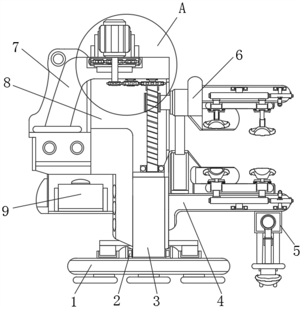
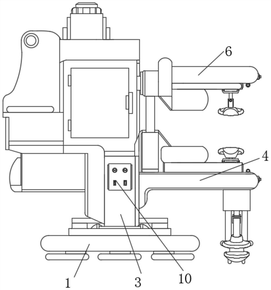
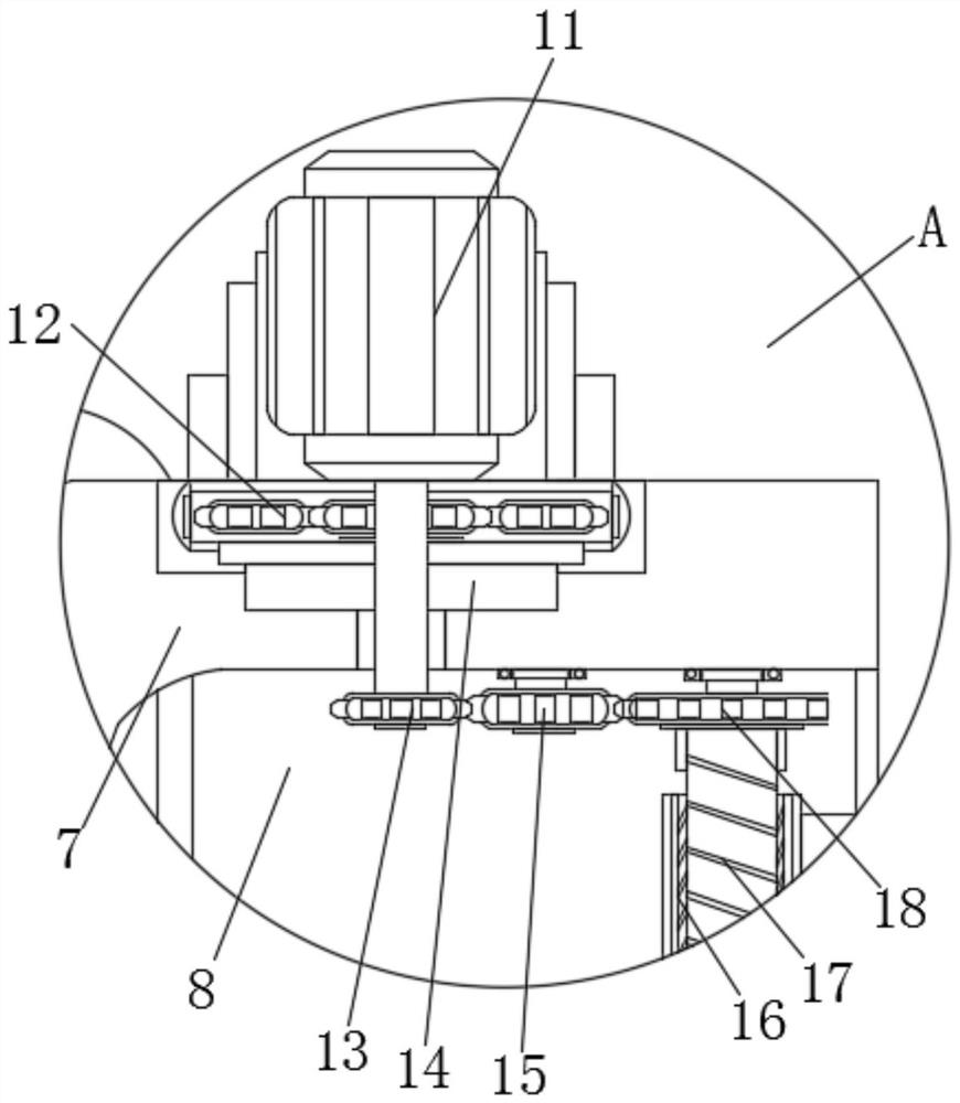
[0035] see Figure 1-8 , the present invention provides a technical solution: a cable splicing crimping machine, including a base 1, a turntable 2 is provided at the middle of the top of the base 1, a mounting seat 3 is provided on the inner side of the turntable 2, and a body 8 is provided on the top of the mounting seat 3 One side of the body 8 is provided with a connecting frame 7, the top of one side of the base 1 is provided with a lower crimping table 4, one side of the top of the body 8 is provided with a low-voltage DC motor 11, and one side of the top of the connecting frame 7 is provided with a The output end of the low-voltage DC motor 11 is connected to the reduction box 12, the bottom of the low-voltage DC motor 11 is provided with a connecting shaft 14, the bottom outside the connecting shaft 14 is provided with a driving gear 13, and the middle position of the top of the body 8 is sleeved with a The driven gear 15 with the driving gear 13 meshing with each other...

Embodiment 2

[0042] see Figure 1-8 , the present invention provides a technical solution: a cable splicing crimping machine, including a base 1, a turntable 2 is provided at the middle of the top of the base 1, a mounting seat 3 is provided on the inner side of the turntable 2, and a body 8 is provided on the top of the mounting seat 3 One side of the body 8 is provided with a connecting frame 7, the top of one side of the base 1 is provided with a lower crimping table 4, one side of the top of the body 8 is provided with a low-voltage DC motor 11, and one side of the top of the connecting frame 7 is provided with a The output end of the low-voltage DC motor 11 is connected to the reduction box 12, the bottom of the low-voltage DC motor 11 is provided with a connecting shaft 14, the bottom outside the connecting shaft 14 is provided with a driving gear 13, and the middle position of the top of the body 8 is sleeved with a The driven gear 15 with the driving gear 13 meshing with each other...


PUM


Abstract

The invention discloses a cable connection crimping machine and a crimping method. The cable connection crimping machine comprises a base, wherein the middle position of the top part of the base is provided with a rotating disc, the inner side of the rotating disc is sleeved with a mounting base, the top part of the mounting base is provided with a machine body, one side of the machine body is provided with a connecting frame, the top part of one side of the base is provided with a lower crimping table, and a low-voltage DC motor is arranged on one side of the top part of the machine body. According to the cable connection crimping machine, through mutual cooperation of crimping adjusting assemblies, two different types of continuous cable molds are assembled at the corresponding positions of the lower crimping table and an upper crimping table, and angle adjustment is carried out on a slide block by utilizing stirring of a stirring wheel and a stirring disc, such that a first crimping die set or a second crimping die set can be adjusted to a corresponding position for press-fit and continuation, and when the first crimping die set and the second crimping die set are not used, the first crimping die set and the second crimping die set can be hidden and protected in semi-arc-shaped hidden grooves, so that dust adhering to the surfaces of parts is reduced.

Description

technical field [0001] The invention relates to the technical fields of electric power engineering, electric engineering construction and electromechanical equipment, in particular to a cable splicing crimping machine and a crimping method. Background technique [0002] The crimping machine is a necessary tool for wire connection and crimping in the power industry in the construction of line infrastructure and line maintenance. The crimping machine is divided into hydraulic crimping machine, large tonnage crimping machine, insulated terminal crimping machine, crimping pliers, split crimping machine, hand hydraulic crimping machine. When working, put the parts to be crimped into the die in the crimping pliers, and the moving mechanism will move the pliers to the appropriate position to be crimped. The hydraulic pump station provides hydraulic high-pressure oil to push the hydraulic pliers to work and perform crimping. [0003] When the current crimping machine is working on ...

Claims


Application Information

Patent Timeline
Patent Type & Authority Applications(China)
IPC IPC(8): H01R43/048
CPCH01R43/048
Inventor 余铁周攀李建波何浩平程勇刘毅
Owner 华容县星星营销传媒中心
Learn More