
Silicon wafer circulating material receiving system and material receiving method

A technology of silicon wafers and material boxes, which is applied in the direction of primary batteries, conveyors, electrochemical generators, etc., can solve the problems of low material receiving efficiency and achieve the effect of improving material receiving efficiency

Pending Publication Date: 2021-09-24
WUXI AUTOWELL TECH
View PDF0 Cites 0 Cited by
  • Summary
  • Abstract
  • Description
  • Claims
  • Application Information

AI Technical Summary

Problems solved by technology

The traditional receiving method is to set up a special silicon wafer receiving mechanism on the side of the main conveying line or manually pick up the silicon wafers from the main conveying line to implement the receiving of silicon wafers. The efficiency of the traditional receiving method of silicon wafers is low

Method used


Image

  • Silicon wafer circulating material receiving system and material receiving method
  • Silicon wafer circulating material receiving system and material receiving method
  • Silicon wafer circulating material receiving system and material receiving method

Examples


Embodiment Construction

[0039] In order to make the above objects, features and advantages of the present invention more comprehensible, the present invention will be further described in detail below in conjunction with the accompanying drawings and specific embodiments.

[0040] In the traditional silicon wafer receiving, a special silicon wafer receiving mechanism is set up on the side of the main conveying line or the silicon wafer is picked up manually from the main conveying line to implement the receiving of silicon wafers, and the receiving efficiency is low.

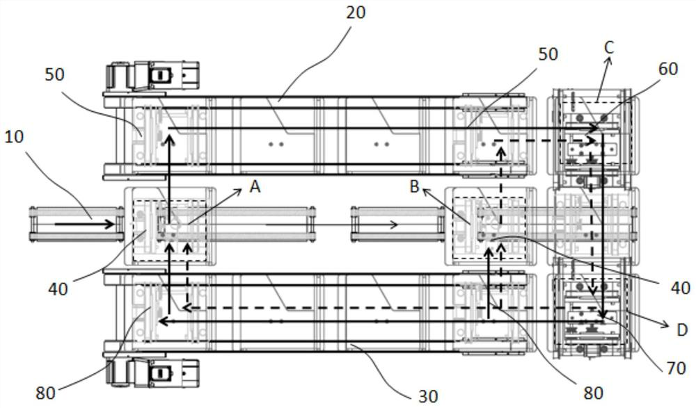
[0041] In view of the defects in the traditional way of receiving silicon wafers, the present invention provides a circular receiving system for silicon wafers, which realizes automatic receiving of silicon wafers and improves the efficiency of receiving materials.

[0042] Such asfigure 1 As shown, the silicon wafer recycling system of the present invention includes a silicon wafer conveying mechanism 10 , a receiving conveying mechani...


PUM


Abstract

The invention provides a silicon wafer circulating material receiving system and material receiving. The system comprises a silicon wafer conveying mechanism, a material receiving conveying mechanism and a backflow conveying mechanism, wherein, the conveying path of the silicon wafer conveying mechanism is provided with a plurality of silicon wafer receiving stations, and the silicon wafer conveying mechanism is configured to convey silicon wafers into material boxes located at the silicon wafer receiving stations; the full material boxes filled with the silicon wafers are reversed to the material receiving conveying mechanism from the silicon wafer receiving stations, and the material receiving conveying mechanism is configured to convey the full material boxes to a material receiving station located at the discharging end of the material receiving conveying mechanism; and the empty material boxes which are moved to be empty at the material receiving station are reversed to a backflow station located at the feeding end of the backflow conveying mechanism, and the backflow conveying mechanism is configured to convey the empty material boxes located at the backflow station towards the silicon wafer receiving stations so that the empty material boxes can flow back to the silicon wafer receiving stations. According to the system, automatic material receiving of the silicon wafers is realized, circulating backflow of the material boxes between the wafer receiving stations and the material receiving station is realized, and the material receiving efficiency is improved.

Description

technical field [0001] The invention relates to the field of battery production, in particular to a silicon chip circulation receiving system and a receiving method. Background technique [0002] After the sorting of the silicon wafers is completed, the silicon wafers need to be removed from the main conveying line of the silicon wafer sorting equipment in time, that is, the receiving of the silicon wafers is completed. The traditional receiving method is to set up a special silicon wafer receiving mechanism on the side of the main conveying line or manually pick up the silicon wafers from the main conveying line to implement the receiving of silicon wafers. The efficiency of the traditional receiving method of silicon wafers is low. Contents of the invention [0003] In order to solve the above-mentioned technical problems, the present invention provides a silicon wafer recycling system on the one hand, which adopts the following technical scheme: [0004] A silicon waf...

Claims


Application Information

Patent Timeline
Patent Type & Authority Applications(China)
IPC IPC(8): B65G37/00B65G65/32B65G69/00B65G41/00H01M10/04H01M6/00
CPCB65G37/00B65G65/32B65G69/00B65G41/002H01M10/04H01M6/00B65G2201/022Y02P70/50
Inventor 李文李昶王美徐飞李泽通薛冬冬韩杰卞海峰
Owner WUXI AUTOWELL TECH
Learn More