Quantitative oiling device and oiling method thereof

A technology of oil injection device and oil injection pipe, which is applied in the direction of distribution device, special distribution device, liquid distribution, transportation or transfer device, etc., and can solve the problems of small oil injection coverage of oil injection device, inconvenient quantitative oil injection treatment, pressurized oil injection work intensity and Pressure and other problems, to achieve the effect of reducing the intensity and pressure of oil injection work, easy to take out, and convenient to fix the limit

Pending Publication Date: 2021-09-24
周贤平
View PDF0 Cites 0 Cited by
  • Summary
  • Abstract
  • Description
  • Claims
  • Application Information

AI Technical Summary

Problems solved by technology

[0003] At present, an oil injection device is designed for better oil injection treatment of electromechanical equipment, but the existing oil injection device is inconvenient for quantitative oil injection treatment, boosted oil injection work intensity and pressure, and at the same time, the oil injection device has a small coverage area of ​​oil injection, and needs to Continuous oiling can only be done by moving the oiling device continuously

Method used


Image

  • Quantitative oiling device and oiling method thereof
  • Quantitative oiling device and oiling method thereof
  • Quantitative oiling device and oiling method thereof

Examples


Embodiment 1

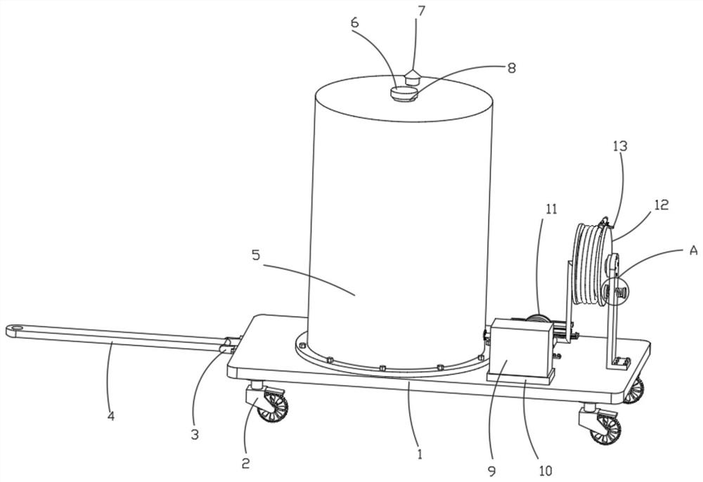
[0043] Such as figure 1 , 2 , a quantitative oiling device shown in 3, 4, 5, 6, 7, including a base 1, the bottom of the base 1 is symmetrically fixedly connected with a universal wheel 2, and one end of the base 1 is connected with a traction structure, and the traction structure includes a first L Shaped plate 3 and traction plate 4, the first L-shaped plate 3 is symmetrically fixedly installed on one end of base 1, the first L-shaped plate 3 is rotatably connected with traction plate 4 through a fixedly connected bearing, and traction plate 4 is connected with the external power structure;

[0044] One end of the top of the base 1 is connected with an oil storage tank 5, the top of the oil storage tank 5 is fixedly connected with an oil injection pipe 8 for oil injection, and the top of the oil injection pipe 8 is movably connected with a cap 6, 6 and 8 can be sealed, The top of the tank is connected with a breather valve 7 for balancing the pressure of the oil storage tan...

Embodiment 2

[0047] Embodiment 2 is a further improvement to Embodiment 1.

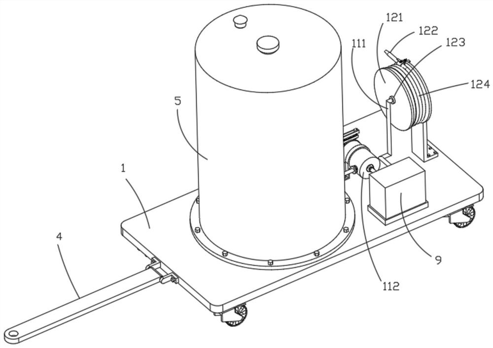
[0048] Such as figure 2 , 3 , 8, the damping winding structure 12 includes a hollow winding roller 121, an oil pipe 122, a sealed bearing 123, a hose 124, a second L-shaped plate 125, a first spring 126, a circular plate 127, a transverse shaft 128, Connecting pipe 129, rubber ring 1210, cross bar 1211, control valve 1212 and connecting sleeve 1213, the second L-shaped plate 125 is fixedly installed on the top of the base 1, and the top of the side wall of the second L-shaped plate 125 rotates through the fixedly connected bearing Connected with a horizontal shaft 128, the horizontal shaft 128 is fixedly connected with a hollow winding roller 121, the left end of the hollow winding roller 121 is fixedly connected with a sealed bearing 123, and the inner wall of the outer ring of the sealed bearing 123 is fixedly connected with a connecting pipe 129, and the connecting pipe 129 The top is fixedly connected with ...

Embodiment 3

[0050] Embodiment 3 is a further improvement to Embodiment 1.

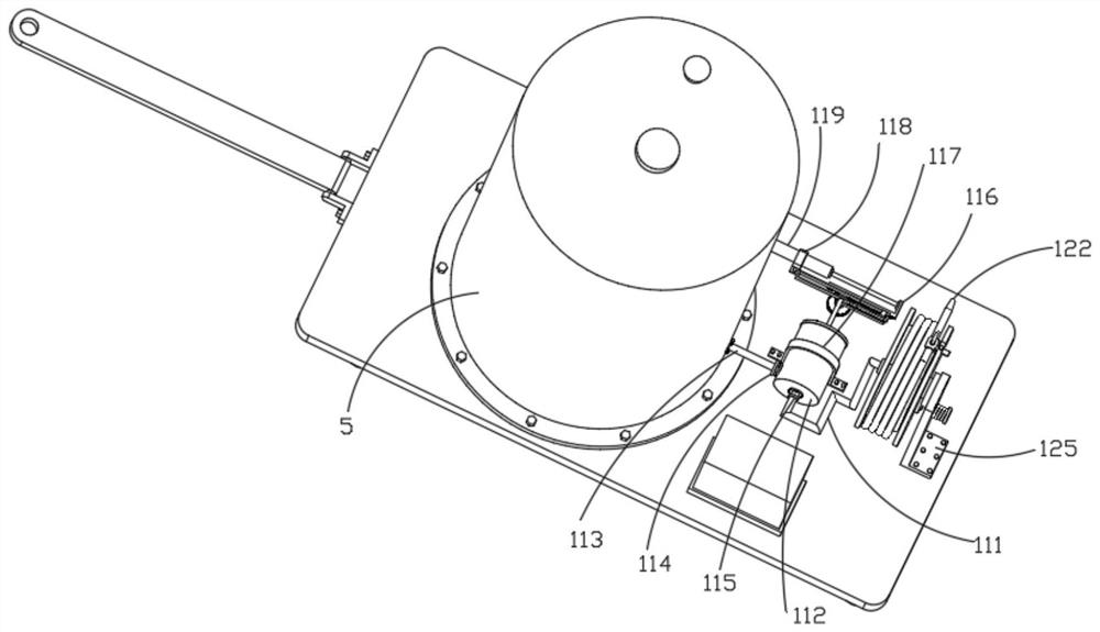
[0051] Such as Figure 9 The hollow winding roller 121 shown is connected with a fixed structure 13 for the fixed connection of the connecting sleeve 1213. The fixed structure 13 includes a lock pin 131, a second spring 132, a horizontal plate 133 and a chute 134. The chute 134 is provided in the hollow winding roller. The side wall of the roller 121, the hollow winding roller 121 is fixedly connected with the second spring 132 at the top of the chute 134, the top of the second spring 132 is fixedly connected with the lock pin 131, and the outer wall of the connecting sleeve 1213 is fixedly connected with the chute 134 fits the horizontal plate 133 that is slidingly connected, and the bottom of the locking pin 131 penetrates the hollow winding roller 121 and is plugged into the top hole of the horizontal plate 133, and the horizontal plate 133 is pulled out from the chute 134 to pull the damping winding structure ...


PUM


Abstract

The invention relates to a quantitative oiling device and an oiling method thereof and belongs to the field of electromechanical equipment maintenance. The quantitative oiling device comprises a base, universal wheels are symmetrically and fixedly connected to the bottom of the base, a traction structure is connected to one end of the base, an oil storage tank is connected to one end of the top of the base, and an oiling pipe used for oiling is fixedly connected to the top of the oil storage tank; and the top of the oiling pipe is movably connected with a cap, the top of the oil storage tank is connected with a breather valve used for balancing the pressure intensity of the oil storage tank, the base is connected with a quantitative structure used for quantitative output, and the quantitative structure is connected with a damping winding structure with the adjustable oiling length. Quantitative oiling treatment is facilitated, and the oiling working intensity and pressure are reduced.

Description

technical field [0001] The invention relates to the field of electromechanical equipment maintenance, in particular to a quantitative oil injection device and an oil injection method. Background technique [0002] Electromechanical equipment generally refers to machinery, electrical appliances, and electrical automation equipment. In construction, it refers to the general term for machinery and pipeline equipment other than geotechnical, carpentry, steel bars, and muddy water. Electromechanical equipment needs regular maintenance during long-term use, and it is usually necessary to fill the electromechanical equipment with oil during the maintenance process. [0003] At present, an oil injection device is designed for better oil injection treatment of electromechanical equipment, but the existing oil injection device is inconvenient for quantitative oil injection treatment, boosted oil injection work intensity and pressure, and at the same time, the oil injection device has ...

Claims


Application Information

Patent Timeline
Patent Type & Authority Applications(China)
IPC IPC(8): B67D7/04B67D7/18B67D7/84B65H75/44
CPCB67D7/04B67D7/18B67D7/84B65H75/4442B65H2701/33
Inventor 周贤平
Owner 周贤平
Why Eureka
Try Eureka