
Continuous wall construction equipment and deviation rectifying device thereof

A technology of construction equipment and deviation correcting device, which is applied in the direction of mechanically driven excavators/dredgers, earth movers/shovels, construction, etc., and can solve the problem of high verticality requirements of diaphragm walls, failure of normal construction, and inability to meet the requirements of diaphragm walls High-precision construction and other issues

Pending Publication Date: 2021-09-24
JIANGSU XCMG CONSTR MASCH RES INST LTD +1
View PDF7 Cites 0 Cited by
  • Summary
  • Abstract
  • Description
  • Claims
  • Application Information

AI Technical Summary

Problems solved by technology

In the construction process of such space-constrained projects, conventional double-wheel milling machines, diaphragm wall grabs and other diaphragm wall construction equipment cannot work normally due to the height of the equipment, and low-profile diaphragm wall construction equipment is often required
[0003] As the excavation depth of the engineering foundation pit continues to increase, the construction depth of the underground diaphragm wall is also increasing, and the verticality requirements for the construction of the diaphragm wall are also getting higher and higher. The conventional correction device of the diaphragm wall construction equipment has been unable to Meet the high-precision construction requirements of low-profile diaphragm wall construction equipment

Method used


Image

  • Continuous wall construction equipment and deviation rectifying device thereof
  • Continuous wall construction equipment and deviation rectifying device thereof

Examples


Embodiment Construction

[0028] The following will clearly and completely describe the technical solutions in the embodiments of the present disclosure with reference to the accompanying drawings in the embodiments of the present disclosure. Apparently, the described embodiments are only some of the embodiments of the present disclosure, not all of them. The following description of at least one exemplary embodiment is merely illustrative in nature and in no way intended as any limitation of the disclosure, its application or uses. Based on the embodiments in the present disclosure, all other embodiments obtained by persons of ordinary skill in the art without creative efforts fall within the protection scope of the present disclosure.

[0029] Relative arrangements of components and steps, numerical expressions and numerical values ​​set forth in these embodiments do not limit the scope of the present disclosure unless specifically stated otherwise. At the same time, it should be understood that, for...


PUM


Abstract

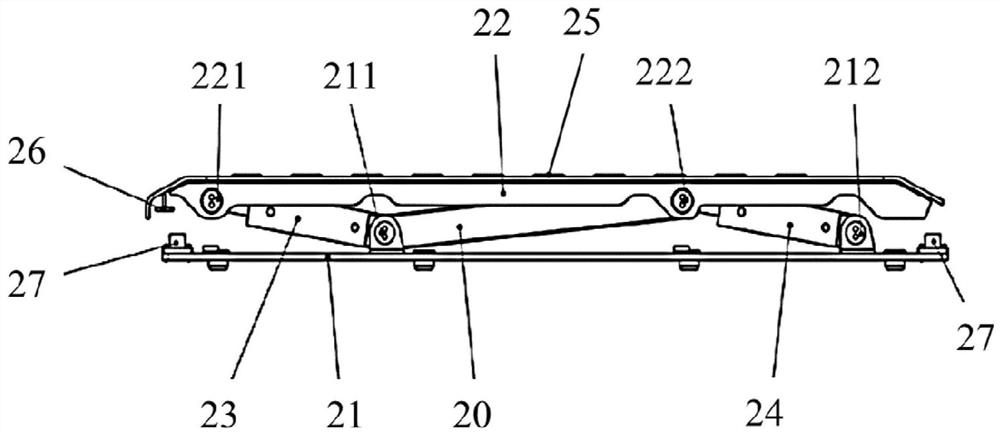
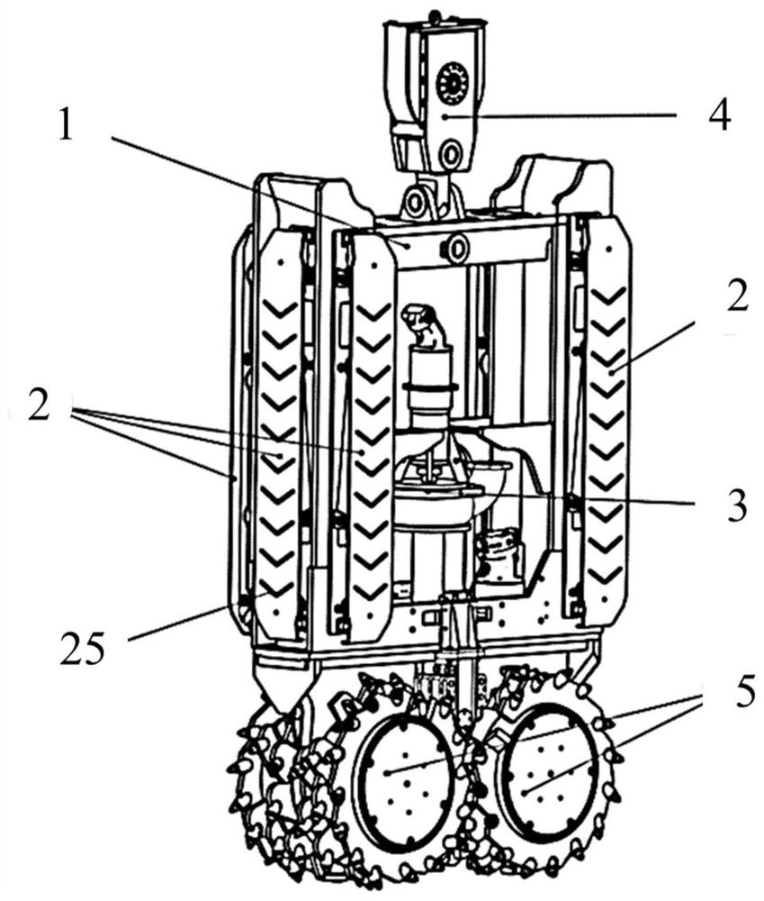
The invention provides continuous wall construction equipment and a deviation rectifying device thereof. The deviation rectifying device comprises a push plate, a first oil cylinder, a second oil cylinder and a connecting rod, wherein the first end of the first oil cylinder is hinged to the push plate around a first hinge axis located on the first side in the thickness direction of the push plate, and the second end of the first oil cylinder is used for being hinged to the continuous wall construction equipment around a second hinge axis parallel to the first hinge axis; the first end of the second oil cylinder is hinged to the push plate around a third hinge axis located on the first side, the third hinge axis is parallel to the first hinge axis and is arranged at an interval with the first hinge axis in the length direction of the push plate, and the second end of the second oil cylinder is used for being hinged to the continuous wall construction equipment around a fourth hinge axis parallel to the first hinge axis; one end of the connecting rod is hinged to the first end of the first oil cylinder around the first hinge axis, the other end of the connecting rod is hinged to the second end of the second oil cylinder around the fourth hinge axis, or one end of the connecting rod is hinged to the first end of the second oil cylinder around the third hinge axis, and the other end of the connecting rod is hinged to the second end of the first oil cylinder around the second hinge axis.

Description

technical field [0001] The present disclosure relates to the field of engineering machinery, in particular to a deviation correcting device for continuous wall construction equipment and continuous wall construction equipment. Background technique [0002] With the application of underground diaphragm wall construction technology in my country's urban construction more and more widely, such as in subway stations, underground shopping malls, etc., more and more infrastructure projects are constructed in places with limited space such as under viaducts and under high-voltage lines. . In the construction process of such space-constrained projects, conventional diaphragm wall construction equipment such as double-wheel slot milling machines and diaphragm wall grabs cannot work normally due to the height of the equipment, and low-profile diaphragm wall construction equipment is often required. [0003] As the excavation depth of the engineering foundation pit continues to increas...

Claims


Application Information

Patent Timeline
Patent Type & Authority Applications(China)
IPC IPC(8): E02F5/02E02F5/08E02F5/14E02F3/18E02F3/24E02F3/26
CPCE02F5/02E02F5/08E02F5/14E02F3/18E02F3/246E02F3/26
Inventor 倪坤苏伟王淑婧
Owner JIANGSU XCMG CONSTR MASCH RES INST LTD
Learn More