
A paper tape rectification control device and rectification method

A paper tape and controller technology, which is applied in the paper tape deviation correction control device and the paper tape deviation correction field, can solve the problems affecting the precision production equipment continuity of the strip processing, the overprint deviation of the printing pattern, and the irregular edge of the strip, etc., to achieve Easy to expand the use of functions, fast response, and convenient operation

Active Publication Date: 2019-07-23
佛山市顺德东叶机电有限公司
View PDF5 Cites 0 Cited by
  • Summary
  • Abstract
  • Description
  • Claims
  • Application Information

AI Technical Summary

Problems solved by technology

[0002] Strips such as paper, plastic film, and textiles are easily affected by uncontrollable forces during the processing process, thus deviating from the original preset reference line, showing a serpentine-like lateral offset, causing the strips to The irregularity of the edges and the deviation of the printing pattern during overprinting seriously affect the accuracy of strip processing and the continuity of normal operation of production equipment
The faster the running speed of the paper tape, the more serious the deviation phenomenon will be. If the deviation cannot be corrected in time, the quality of the finished product will be seriously affected, and the consumption of materials will be increased, resulting in a large amount of waste products.
The deviation of the strip is the result of the joint action of many factors, and it exists objectively. It is very difficult to prevent the deviation from happening.
However, it is difficult to ensure the correct operation of the tape through the machine itself. Generally, an external correction system is used to detect and control the entire paper tape running process in real time.

Method used


Image

  • A paper tape rectification control device and rectification method
  • A paper tape rectification control device and rectification method
  • A paper tape rectification control device and rectification method

Examples


Embodiment Construction

[0036] specific implementation

[0037] The present invention will be described in detail below in conjunction with the accompanying drawings and specific embodiments.

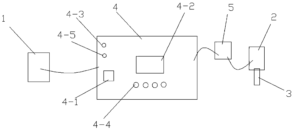
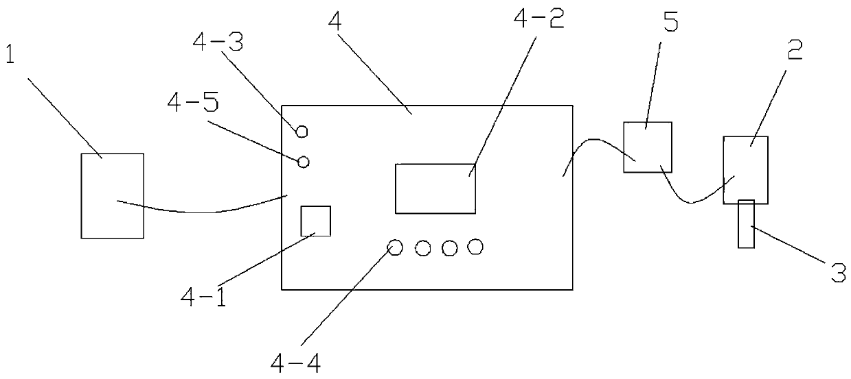
[0038] A paper tape deviation correction control device of the present invention, such as figure 1 As shown, it includes an ultrasonic sensor 1, the ultrasonic sensor 1 is connected with a control system 4, the control system 4 is connected with a stepper motor driver 5, the stepper motor driver 5 is connected with a stepper motor 2, and the output shaft of the stepper motor 2 is connected with a Ball screw 3.

[0039] The control system 4 comprises a controller 4-1, and the controller 4-1 is connected with a liquid crystal display 4-2, a communication module, a first indicator light 4-3, a second indicator light 4-5 and a reset switch 4-4; Switch 4-4 is connected with stepping motor 2.

[0040] The model number of the ultrasonic sensor 1 is AE-210.

[0041] The controller 4-1 is a chip of model STC12C5A60...


PUM


Abstract

The invention discloses a paper tape deviation correction control device. The paper tape deviation correction control device comprises an ultrasonic sensor; the ultrasonic sensor is connected with a control system; the control system is connected with a stepper motor driver; the stepper motor driver is connected with a stepper motor; and the output shaft of the stepper motor is connected with a ball screw. The paper tape deviation correction control device is stable in performance and reliable in operation, the deviation correction system is a closed loop control system, the sensor serves as feedback and can acquire and transmit information in real time, and the deviation correction device is ensured to be in a dynamic monitoring state. A power supply module provides different levels of DC power for the whole deviation correction control system, and the system is ensured to work normally. By adopting the deviation correction method of the invention, the phenomenon that the tape material deviates due to effects of various uncontrollable forces during the processing process can be solved, the overprint accuracy during the printing process is ensured, the product quality is improved, and the material waste is reduced.

Description

technical field [0001] The invention relates to the technical field of printing equipment, in particular to a paper tape deviation correction control device, and also relates to a method for using the paper tape deviation correction control device to perform paper tape deviation correction. Background technique [0002] Strips such as paper, plastic film, and textiles are easily affected by uncontrollable forces during the processing process, thus deviating from the original preset reference line, showing a serpentine-like lateral offset, causing the strips to The irregularity of the edges and the deviation of the printing pattern during overprinting have seriously affected the accuracy of strip processing and the continuity of normal operation of production equipment. The faster the running speed of the paper tape, the more serious the deviation phenomenon will be. If the deviation cannot be corrected in time, the quality of the finished product will be seriously affected, ...

Claims


Application Information

Patent Timeline
Patent Type & Authority Patents(China)
IPC IPC(8): G05B19/4065
CPCG05B19/4065G05B2219/37616
Inventor 侯和平邓瑞徐卓飞薛伟
Owner 佛山市顺德东叶机电有限公司
Learn More