TCP robot tool tail end 3D and 5D error correction system and error correction method thereof
A robot and tool technology, applied in the 5D deviation correction system, TCP robot tool end 3D field, can solve the problems of original state error, long adjustment time, etc., achieve fast deviation correction speed, high deviation correction precision, and fast data reading and writing processing speed
- Summary
- Abstract
- Description
- Claims
- Application Information
AI Technical Summary
Problems solved by technology
Method used
Image
Examples
Embodiment 1
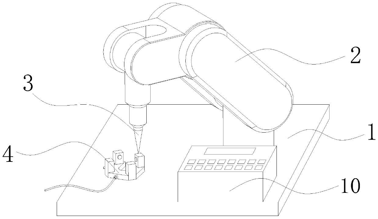
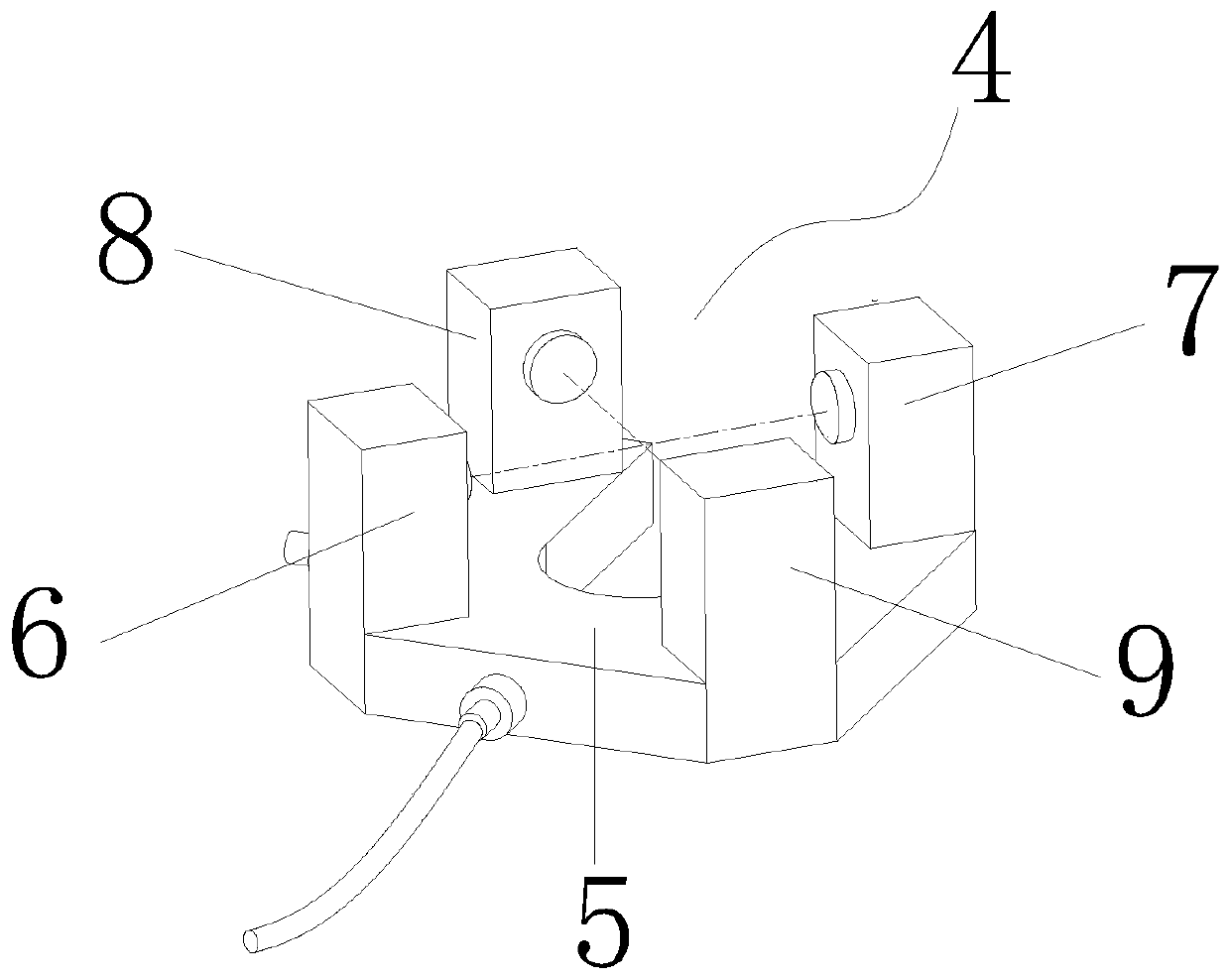
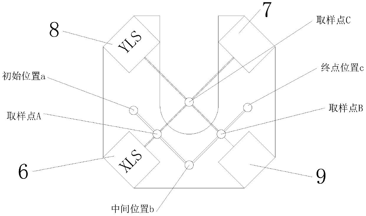
[0032] see Figure 1-5 , the present invention provides the following technical solutions: a TCP robot tool end 3D, 5D deviation correction system, including a reference platform 1, a mechanical arm 2, a cross sensor 4 and a calculation controller 10, characterized in that: the top of the reference platform 1 is provided with a mechanical Arm 2, the moving end of the mechanical arm 2 is equipped with a guide needle 3, and the plane of the reference platform 1 is fixedly installed with a cross sensor 4, and the moving end of the mechanical arm 2 is located above the cross sensor 4; the cross sensor 4 includes a group of opposite first A laser emitting end 6 and a first laser receiving end 7, another set of oppositely positioned second laser emitting ends 8 and second laser receiving ends 9, the first laser emitting end 6 emits a light beam XLS pointing to the first laser receiving end 7, The second laser emitting end 8 emits light beam YLS and points to the second laser receivi...
Embodiment 2
[0043] A deviation correction method for a 3D and 5D deviation correction system at the end of a TCP robot tool. The steps S1 to S4 are the same, and the difference between S5 and S7 is that: after the guide needle 3 is offset, the mechanical arm 2 carries the guide needle 3 to follow the reference trajectory first. Draw a circle normally, and then draw a circle again after the Z-axis descends to a set distance. The actual tilt angle of the needle can be known through the centers of the two circles. After angle compensation, compare it with the reference to perform X-axis and Y-axis deviation correction, and finally perform Z-axis deviation correction. .
Embodiment 3
[0045] A deviation correction method for a 3D and 5D deviation correction system at the end of a TCP robot tool, the calculation formula of the process is:
[0046] The state change (RX / RY / X / Y / Z) of the tool at the end of the robot arm 2 is caused by external force collision or replacement of the processing tool during use. The guide needle 3 draws L in the cross sensor 4, and through the above The method is calculated to obtain (RX / RY / X / Y / Z) five offset values, and the five offset values with the robot arm 2 are corrected, so that the guide needle 3 returns to the correct initial processing state.
PUM
 Abstract
Description
Claims
Application Information
 - R&D
- Intellectual Property
- Life Sciences
- Materials
- Tech Scout
- Unparalleled Data Quality
- Higher Quality Content
- 60% Fewer Hallucinations
Browse by: Latest US Patents, China's latest patents, Technical Efficacy Thesaurus, Application Domain, Technology Topic, Popular Technical Reports.
© 2025 PatSnap. All rights reserved.Legal|Privacy policy|Modern Slavery Act Transparency Statement|Sitemap|About US| Contact US: help@patsnap.com


