
Distributed optical fiber sensor with controllable temperature fluctuation and temperature measurement system and method

A distributed optical fiber, temperature fluctuation technology, applied in thermometers, thermometers with physical/chemical changes, instruments, etc., can solve problems such as imperfections, and achieve the effect of controllable temperature fluctuations

Active Publication Date: 2017-03-01
WEIHAI BEIYANG ELECTRIC GRP CO LTD BEIJING BRANCH
View PDF11 Cites 0 Cited by
  • Summary
  • Abstract
  • Description
  • Claims
  • Application Information

AI Technical Summary

Problems solved by technology

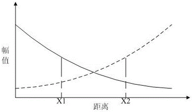
[0003]Although the research on Raman-type distributed fiber optic temperature sensors is relatively mature, there are still imperfections. At present, the development direction of distributed fiber optic temperature sensors is long-distance , high precision, and high precision means high temperature fluctuation and high spatial resolution. The spatial resolution is determined by the laser pulse width, which can be solved by narrow pulse laser; realize long distance and high temperature fluctuation, and ultimately pursue high signal Noise ratio, at present, the temperature fluctuation of ordinary distributed optical fiber temperature sensors increases with the increase of the measurement distance, that is, the temperature fluctuation at the nominal measurement distance of the system is the nominal temperature fluctuation of the system
[0004] In 2011, the Italian Soto team announced its latest research results "High-Performance Raman-Based Distributed Fiber-Optic Sensing Under a Loop Scheme Using Anti-Stokes LightOnly", a single-channel anti-Stokes Raman optical fiber transmission with a double-ended correction scheme Inductive system, although this study has a good correction effect on loss, etc., but the temperature fluctuation still has the characteristics that the middle is better than the two ends.

Method used


Image

  • Distributed optical fiber sensor with controllable temperature fluctuation and temperature measurement system and method
  • Distributed optical fiber sensor with controllable temperature fluctuation and temperature measurement system and method
  • Distributed optical fiber sensor with controllable temperature fluctuation and temperature measurement system and method

Examples


Embodiment Construction

[0036] The present invention will be further described below in conjunction with the accompanying drawings and specific implementation.

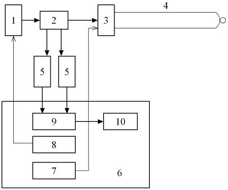
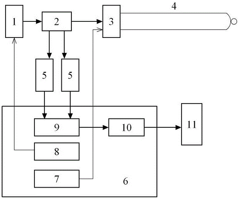
[0037] as attached figure 1 As shown, the present invention proposes a distributed optical fiber sensor with controllable temperature fluctuation and a temperature measurement system and method, including a pulsed fiber laser 1, a wavelength division multiplexer 2, a 1*2 optical switch 3, and a sensing fiber 4 , a photoelectric receiving module 5 and a data acquisition card 6, characterized in that the light emitted by the pulsed fiber laser 1 enters the 1*2 optical switch 3 through the com end of the wavelength division multiplexer 2, and the two output ports of the 1*2 optical switch 3 respectively connected to the two ends of the sensing fiber 4, the photoelectric receiving module 5 is connected to the back signal output end of the wavelength division multiplexer 2, and the control signal output end of the data acquisition card 6 is connect...


PUM

PropertyMeasurementUnit
wavelengthaaaaaaaaaa

Abstract

The invention relates to the technical field of optical fiber temperature measurement, in particular to a distributed optical fiber temperature sensor and temperature measurement which can improve the correction accuracy of the middle section of the sensing optical fiber and retain the temperature fluctuation of the fluctuation index at both ends of the sensing optical fiber. The system and method are characterized in that the light emitted by the pulsed fiber laser enters the 1*2 optical switch through the com port of the wavelength division multiplexer, and the two output ends of the 1*2 optical switch are respectively connected to the two ends of the sensing fiber. The receiving module is connected to the back signal output end of the wavelength division multiplexer, one control signal output end of the data acquisition card is connected to the pulsed fiber laser, and the other control signal output end of the data acquisition card is connected to the 1*2 optical switch Connection, the signal output end of the photoelectric receiving module is connected with the data acquisition end of the data acquisition card. Compared with the existing technology, the correction operation of the middle section of the optical fiber is realized, and the fluctuation index at both ends of the optical fiber is retained, so that the system can be used. Control temperature fluctuations.

Description

technical field [0001] The invention relates to the technical field of optical fiber temperature measurement, in particular to a distributed optical fiber sensor and a temperature measurement system capable of improving the calibration accuracy of the middle section of the sensing optical fiber and retaining the temperature fluctuation of the fluctuation index at both ends of the sensing optical fiber. and methods. Background technique [0002] As we all know, the distributed optical fiber temperature sensor is a kind of optical fiber sensing system developed in recent years for real-time measurement of the spatial temperature field. This system uses Raman scattering effect and OTDR technology to realize distributed measurement of the temperature field where the sensitive optical fiber is located. Compared with traditional electrical temperature sensors, optical fiber temperature sensors have the advantages of high sensitivity, anti-electromagnetic interference, light weight...

Claims


Application Information

Patent Timeline
Patent Type & Authority Patents(China)
IPC IPC(8): G01K11/32G01K11/324
Inventor 王建强李德和夏俊玲
Owner WEIHAI BEIYANG ELECTRIC GRP CO LTD BEIJING BRANCH
Learn More