
A dust detection system applied to construction site

A detection system and construction site technology, applied in measuring devices, suspension and porous material analysis, scientific instruments, etc., can solve problems such as dust pollution, inability to obtain distance sensor values, lung injury, etc., and achieve accurate dust values

Active Publication Date: 2022-03-08
江苏铁军软件科技有限公司 +1
View PDF29 Cites 0 Cited by
  • Summary
  • Abstract
  • Description
  • Claims
  • Application Information

AI Technical Summary

Problems solved by technology

[0002] In some sites such as construction sites, decoration construction or road and bridge construction, various types of construction waste are often accompanied by dust pollution. Through observation, we can also find that the source of dust is usually accompanied by huge noise , such as cutting machines, punching machines, various crushing devices, etc., will generate extremely serious dust while generating loud noises. The damage of dust to the body is obvious, and it can directly cause huge damage to the lungs of the human body, so in Similar to construction sites, various mines and other places prone to dust generation, dust detection systems are usually installed to detect the density of dust in the air at any time and continuously remind the staff to protect their own health. This detection is usually through sensors. The measurement results are only limited to the value of the dust attached to the sensor, and the value at a position farther away from the sensor cannot be obtained
[0003] However, the conventional dust detection system usually cannot be as close as possible to the point where the dust is generated, that is, the location where the huge noise is generated. Part of the dust falls back to the bottom or adheres to other places, so that the value detected by the detection system cannot correctly reflect the harmfulness of the dust

Method used


Image

  • A dust detection system applied to construction site
  • A dust detection system applied to construction site
  • A dust detection system applied to construction site

Examples


Embodiment Construction

[0029] The following will clearly and completely describe the technical solutions in the embodiments of the present invention with reference to the accompanying drawings in the embodiments of the present invention. Obviously, the described embodiments are only some, not all, embodiments of the present invention. Based on the embodiments of the present invention, all other embodiments obtained by persons of ordinary skill in the art without making creative efforts belong to the protection scope of the present invention.

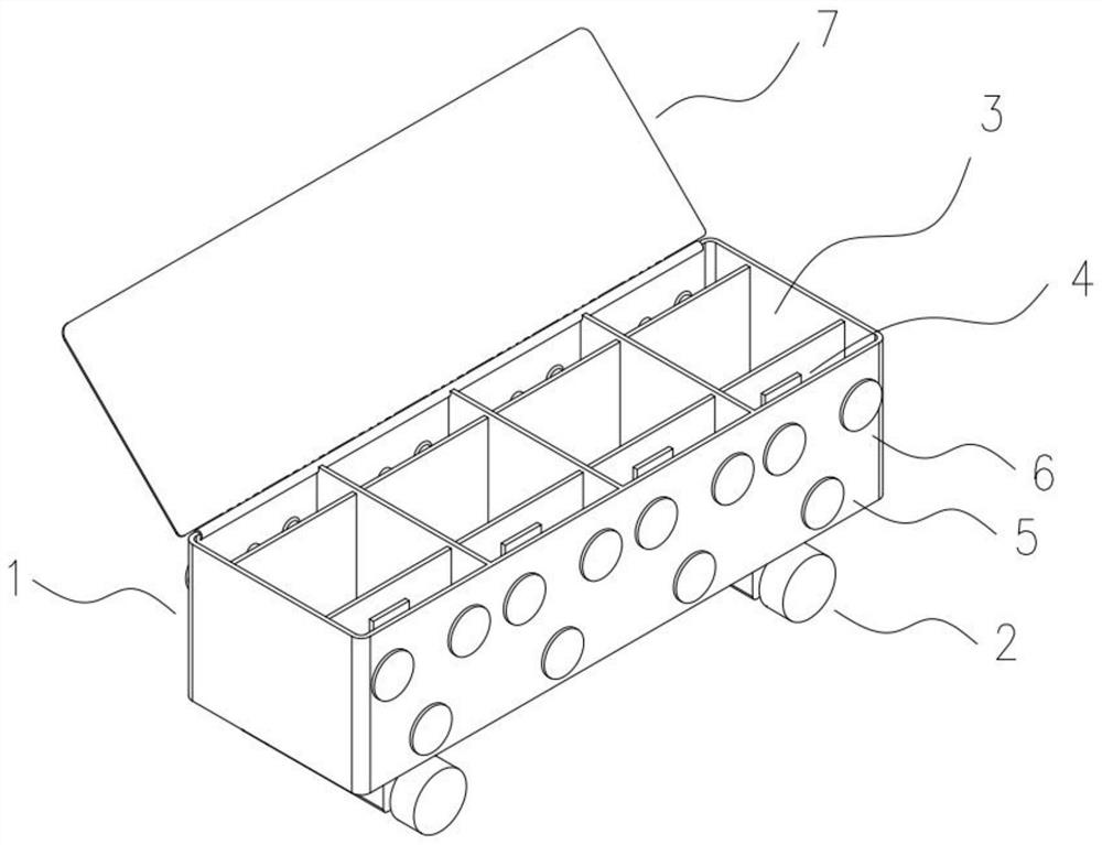
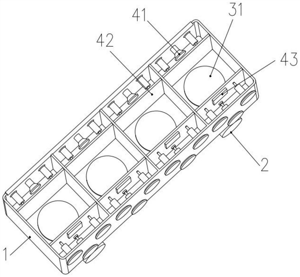
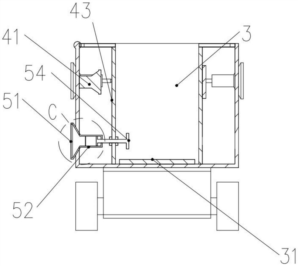
[0030] see Figure 1 to Figure 5 , the present invention provides a technical solution: a dust detection system applied to the construction site, including a system chassis 1, wheels 2 are arranged at the bottom four corners of the system chassis 1, and the system chassis 1 is evenly divided into a plurality of detection boxes 3. Each detection box 3 is equipped with a light detection device 4 and a dust flow device 5, and above the dust flow device 5 is also ...


PUM


Abstract

The invention discloses a dust detection system applied to a construction site, relates to the field of dust detection equipment, and includes a system case, wheels are arranged at the four corners of the bottom of the system case, and the inside of the system case is evenly divided into a plurality of detection boxes, each The detection box is equipped with light detection equipment and dust flow equipment, above the dust flow equipment is also equipped with dust anti-adhesion equipment, and the light detection equipment is used to detect the dust density in the air under the action of the dust flow equipment and The light detection equipment is not covered by the dust through the function of the anti-adhesion device of the dust. The invention can flexibly move to the place with the most serious dust pollution on the construction site polluted by the dust, and eliminate external factors such as wind and dust by measuring multiple sets of data. Influenced by the influence of dust, a more accurate value of dust can be obtained, and the huge noise generated by dust can be absorbed, and it can be used in dust detection to improve the accuracy of dust detection.

Description

technical field [0001] The invention relates to the field of dust detection equipment, in particular to a dust detection system applied to construction sites. Background technique [0002] In some sites such as construction sites, decoration construction or road and bridge construction, various types of construction waste are often accompanied by dust pollution. Through observation, we can also find that the source of dust is usually accompanied by huge noise , such as cutting machines, punching machines, various crushing devices, etc., will generate extremely serious dust while generating loud noises. The damage of dust to the body is obvious, and it can directly cause huge damage to the lungs of the human body, so in Similar to construction sites, various mines and other places prone to dust generation, dust detection systems are usually installed to detect the density of dust in the air at any time and continuously remind the staff to protect their own health. This detect...

Claims


Application Information

Patent Timeline
Patent Type & Authority Patents(China)
IPC IPC(8): G01N15/06
CPCG01N15/06G01N15/075
Inventor 蔡建红宋娟吴旭黄新国
Owner 江苏铁军软件科技有限公司
Learn More