Optical imaging lens group and imaging system

An optical imaging and lens group technology, applied in optics, optical components, instruments, etc., can solve problems such as poor stability, achieve high imaging quality, ensure optical performance, and stabilize optical performance.

Active Publication Date: 2021-09-24
GUANGDONG XUYE OPTOELECTRONICS TECH
View PDF1 Cites 0 Cited by
  • Summary
  • Abstract
  • Description
  • Claims
  • Application Information

AI Technical Summary

Problems solved by technology

[0004] Aiming at the deficiencies of the prior art, the present invention provides an optical imaging lens group and an

Method used


Image

  • Optical imaging lens group and imaging system
  • Optical imaging lens group and imaging system
  • Optical imaging lens group and imaging system

Examples


Example Embodiment

[0109] Embodiment one

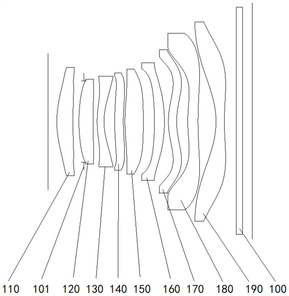
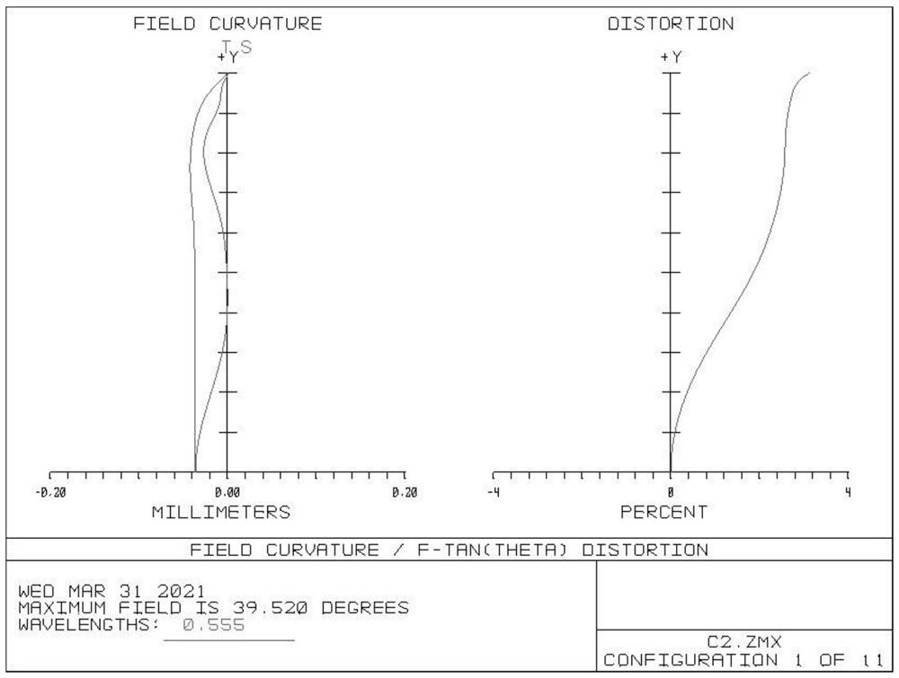
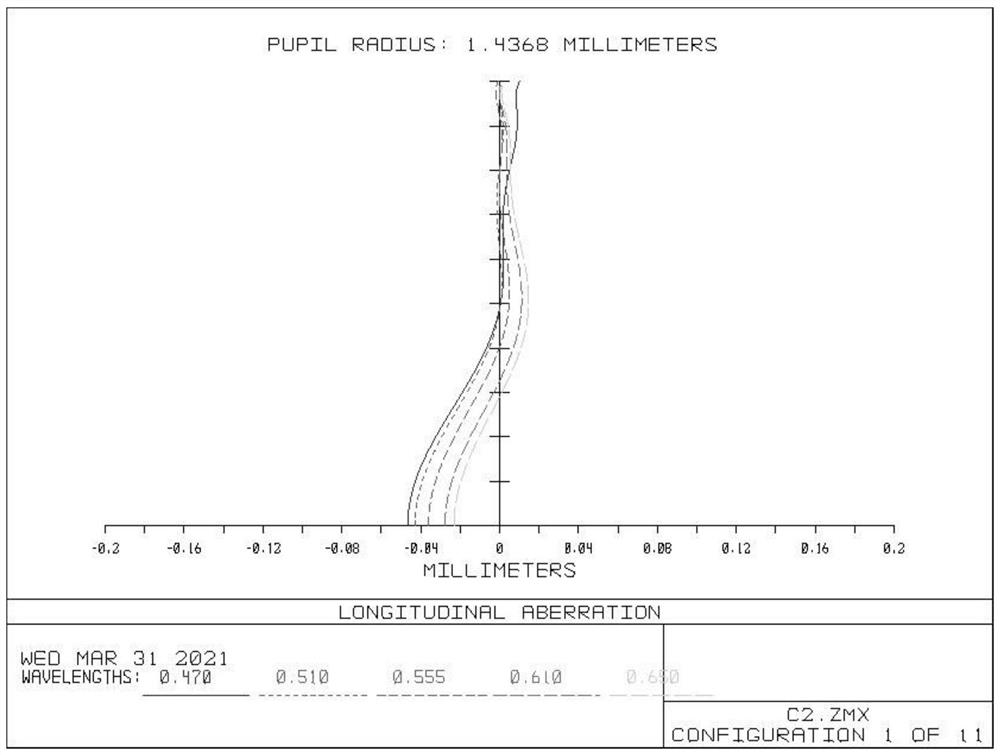
[0110] see Figure 1 to Figure 3 , figure 1 It shows a schematic diagram of an optical imaging lens group according to Embodiment 1 of the present invention, figure 2 From left to right are the astigmatism and distortion curves of an optical imaging lens group according to Embodiment 1 of the present invention, image 3 It is a spherical aberration curve diagram of an optical imaging lens group according to Embodiment 1 of the present invention.

[0111] In the embodiment of the present invention, the optical imaging lens group sequentially includes a first lens 110, a diaphragm 101, a second lens 120, a third lens 130, a fourth lens 140, a fifth lens 150, and a sixth lens from the object side to the image side. 160 , the seventh lens 170 , the eighth lens 180 and the ninth lens 190 . Wherein, each surface from the object side of the first lens 110 to the image side of the ninth lens 190 is aspherical.

[0112] Specifically, the surface type of ea...

Example Embodiment

[0137] Embodiment two

[0138] see Figure 4 to Figure 6 , Figure 4 A schematic diagram of an optical imaging lens group according to Embodiment 2 of the present invention is shown, Figure 5 From left to right are the astigmatism and distortion curves of an optical imaging lens group according to Embodiment 2 of the present invention, Image 6 It is a spherical aberration curve diagram of an optical imaging lens group according to Embodiment 2 of the present invention.

[0139] In the embodiment of the present invention, the optical imaging lens group sequentially includes a first lens 210, a diaphragm 201, a second lens 220, a third lens 230, a fourth lens 240, a fifth lens 250, and a sixth lens from the object side to the image side. 260 , the seventh lens 270 , the eighth lens 280 and the ninth lens 290 . Wherein, each surface from the object side of the first lens 210 to the image side of the ninth lens 290 is aspherical.

[0140] Specifically, the surface type of e...

Example Embodiment

[0161] Embodiment Three

[0162] see Figure 7 to Figure 9 , Figure 7 It shows a schematic diagram of an optical imaging lens group according to Embodiment 3 of the present invention, Figure 8 From left to right is the astigmatism and distortion curve diagram of an optical imaging lens group according to Embodiment 3 of the present invention, Figure 9 It is a spherical aberration curve diagram of an optical imaging lens group according to Embodiment 3 of the present invention.

[0163] In the embodiment of the present invention, the optical imaging lens group sequentially includes a first lens 310, a diaphragm 301, a second lens 320, a third lens 330, a fourth lens 340, a fifth lens 350, and a sixth lens from the object side to the image side. 360 , a seventh lens 370 , an eighth lens 380 and a ninth lens 390 . Wherein, each surface from the object side of the first lens 310 to the image side of the ninth lens 390 is aspherical.

[0164] Specifically, the surface type ...


PUM


Abstract

The invention discloses an optical imaging lens group and an imaging system, and the optical imaging lens group comprises a first lens to a ninth lens. The first lens and the eighth lens which have positive refractive power, and the object side surfaces and the image side surfaces of the first lens and the eighth lens are convex surfaces and concave surfaces respectively; the second lens and the fifth lens have positive refractive power, and the object side surfaces of the second lens and the fifth lens are convex surfaces; the third lens, the fourth lens and the ninth lens have negative refractive power, and object side surfaces and image side surfaces of the third lens, the fourth lens and the ninth lens are convex surfaces and concave surfaces respectively; the sixth lens has positive refractive power, and the object side surface and the image side surface of the sixth lens are respectively a concave surface and a convex surface; the object side surface and the image side surface of the seventh lens are a convex surface and a concave surface respectively; the optical imaging lens group satisfies the following relational expressions that TTL/f is larger than 1.0 and smaller than 2.0; wherein TTL represents the total optical length of the optical imaging lens group, and f represents the focal length of the optical imaging lens group. According to the invention, the optical imaging lens group not only has an imaging effect which can be achieved by multiple lenses, but also can ensure stable optical performance, so that high imaging quality is provided, and meanwhile, the light and thin market requirements are met.

Description

technical field [0001] The invention relates to the technical field of optical imaging, in particular to an optical imaging lens group and an imaging system. Background technique [0002] With the vigorous development of smart phones, people cannot do without smart phones in their work and life. Especially with the increasing popularity of new media industries such as short videos, smart phones are required to be more portable and lighter. Therefore, smart phones And the miniaturization requirements of the imaging system carried in it are getting higher and higher. [0003] Since the greater the number of lenses, the higher the manufacturing cost and difficulty of the imaging system, so the current imaging system usually does not exceed seven lenses. However, the imaging effect of the seven-chip imaging system has been difficult to meet today's market demand. Therefore, how to ensure the stability of the imaging system while increasing the number of lenses to meet the mark...

Claims


Application Information

Patent Timeline
IPC IPC(8): G02B13/00G02B13/18
CPCG02B13/0045G02B13/18
Inventor 林肖怡袁嘉华张龙陈天谋邓敏乐
Owner GUANGDONG XUYE OPTOELECTRONICS TECH
Why Eureka
Try Eureka