Vapor chamber and electronic equipment

A technology of electronic equipment and vapor chamber, which is applied in circuits, electrical components, electric solid devices, etc., can solve the problems of large evaporation thermal resistance of VC capillary structure, and VC performance does not meet the needs of heat dissipation, so as to reduce the evaporation thermal resistance and increase the thermal conductivity. The effect of large evaporation area

Active Publication Date: 2021-09-24
ZTE CORP
View PDF6 Cites 3 Cited by
  • Summary
  • Abstract
  • Description
  • Claims
  • Application Information

AI Technical Summary

Problems solved by technology

[0005] The purpose of the embodiments of the present invention is to provide a vapor chamber to solve the technical problem in the prior art that the VC capillary structure evaporation heat resistance is too large, so that the performance of VC does not meet the heat dissipation requirements
[0006] Another object of the embodiments of the present invention is to provide an electronic device to solve the technical problem in the prior art that the VC capillary structure evaporation heat resistance is too large, so that the performance of VC does not meet the heat dissipation requirements

Method used


Image

  • Vapor chamber and electronic equipment
  • Vapor chamber and electronic equipment
  • Vapor chamber and electronic equipment

Examples


Embodiment Construction

[0034] In order to make the purpose, technical solutions and advantages of the embodiments of the present invention clearer, the technical solutions in the embodiments of the present invention will be clearly and completely described below in conjunction with the drawings in the embodiments of the present invention. Obviously, the described embodiments It is a part of embodiments of the present invention, but not all embodiments. Based on the embodiments of the present invention, all other embodiments obtained by persons of ordinary skill in the art without creative efforts fall within the protection scope of the present invention.

[0035] In the description of the present invention, it should be understood that the terms "comprising" and "having" and any variations thereof are intended to cover a non-exclusive inclusion, for example, a process comprising a series of steps or units, A method, system, product or device is not necessarily limited to those steps or elements expl...


PUM


Abstract

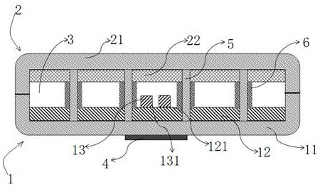
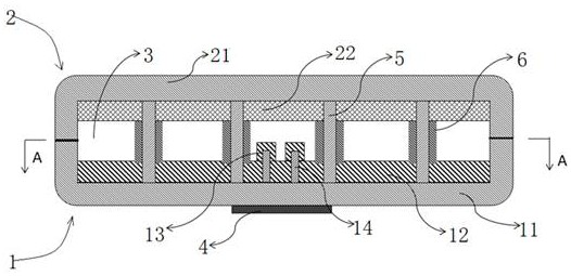
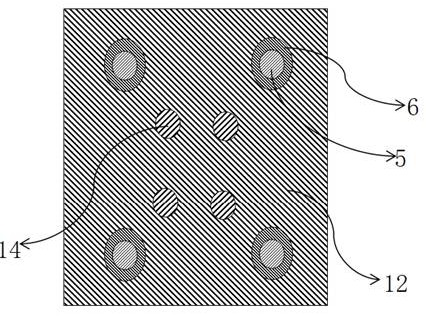
The invention relates to the technical field of heat dissipation, and provides a vapor chamber and electronic equipment, the vapor chamber comprises a first shell and a second shell which are oppositely arranged, and the first shell and the second shell define a closed cavity; the first shell comprises a bottom wall used for making contact with a heat source, the second shell is provided with a top wall right opposite to the bottom wall, a first capillary structure is arranged on the bottom wall and comprises a heat source area capillary structure and a non-heat source area capillary structure, and the heat source area capillary structure comprises a plurality of convex capillary structures and/or a plurality of first concave capillary structures. According to the vapor chamber, a plurality of convex capillary structures and/or a plurality of first concave capillary structures are arranged on the heat source area capillary structure of the first capillary structure of an evaporation area over the VC heat source, so that the evaporation area of a working medium in the VC is increased, and the evaporation thermal resistance of the working medium in the VC is reduced; the heat dissipation problem of the VC in a high-power-consumption and high-heat-flux chip application scene is solved.

Description

technical field [0001] The invention belongs to the technical field of heat dissipation, and more specifically relates to a uniform temperature plate and electronic equipment. Background technique [0002] With the development of electronic products in the electronics industry towards larger capacity and higher performance, the degree of integration of electronic product equipment is getting higher and higher, and the power consumption of devices continues to increase significantly, especially for some multi-function chips, the integration level is also getting higher and higher , which also leads to a continuous increase in heat flux density, which poses a severe challenge to heat dissipation technology, especially in air-cooled systems, where high-power devices face the problem of excessive thermal resistance (excessive temperature rise) from the air side to the chip side. [0003] Vacuum Chamber (Vapor Chamber; VC) also known as vapor chamber is mainly composed of shell, ...

Claims


Application Information

Patent Timeline
Patent Type & Authority Applications(China)
IPC IPC(8): H01L23/427H05K7/20
CPCH01L23/427H05K7/2029H05K7/20309
Inventor 孙振李碧莹李帅徐青松
Owner ZTE CORP
Why Eureka
Try Eureka