Liquid cooling heat dissipation device of orthogonal architecture subrack

A liquid-cooling heat dissipation and liquid-cooling technology, which is applied in cooling/ventilation/heating transformation, electrical equipment structural parts, electrical components, etc. , to achieve the effect of less space occupation, flexible solution and high heat dissipation efficiency

Pending Publication Date: 2020-11-24
南京中新赛克科技有限责任公司
View PDF0 Cites 0 Cited by
  • Summary
  • Abstract
  • Description
  • Claims
  • Application Information

AI Technical Summary

Problems solved by technology

As the power of heating devices increases, due to the limitation of the size and heat dissipation capacity of air-cooled radiators, conventional air-cooled heat dissipation solutions cannot meet the thermal reliability requirements of devices, which in turn leads to device overheating, equipment downtime and other failures
Based on the above, it can be seen that when encountering this kind of heat dissipation problem, the heat dissipation of this type of equipment cannot be solved by conventional air cooling solutions.

Method used


Image

  • Liquid cooling heat dissipation device of orthogonal architecture subrack
  • Liquid cooling heat dissipation device of orthogonal architecture subrack
  • Liquid cooling heat dissipation device of orthogonal architecture subrack

Examples


Embodiment 1

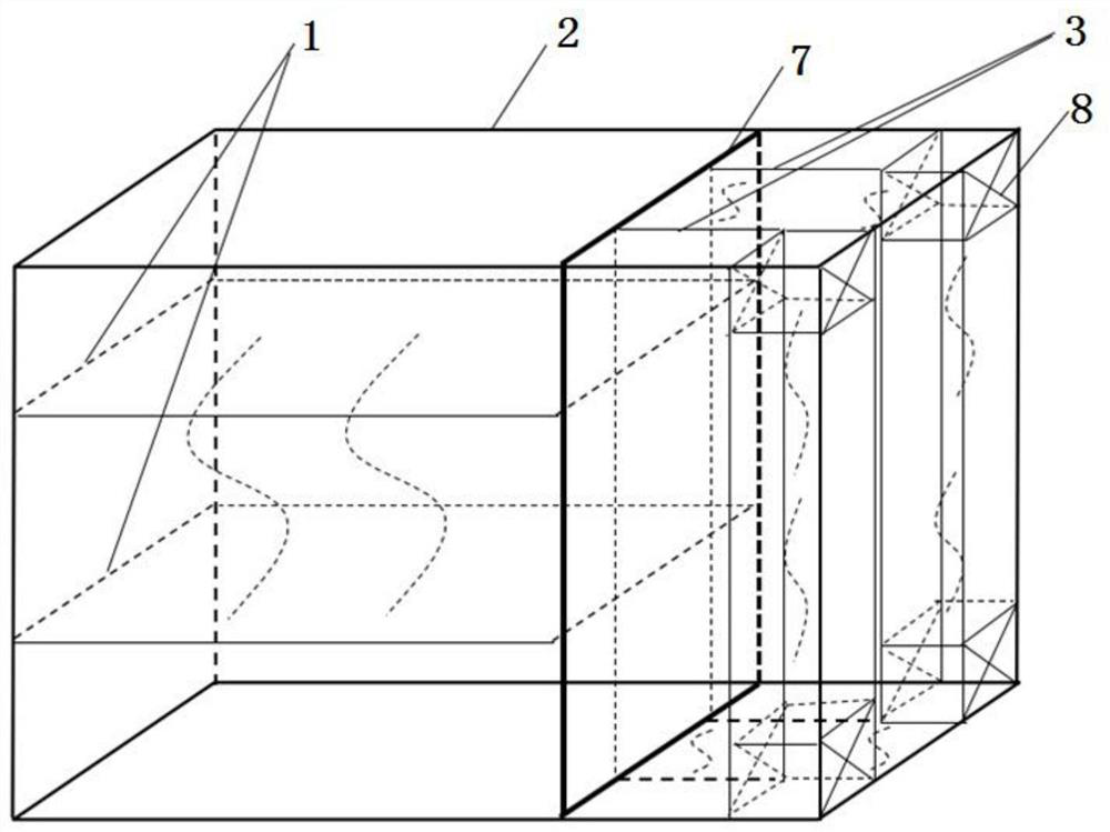
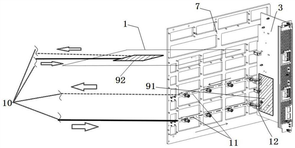
[0025] like image 3 Shown is a schematic diagram of the internal structure of the orthogonal structure sub-box liquid cooling heat dissipation device according to the present invention, the device includes an orthogonal structure sub-box and a liquid cooling heat dissipation device. The orthogonal structure subrack includes a box body, a line card 1, a keel 7, and a switch board 3. The line card 1 contains heat-generating devices, and the switch board 3 also contains heat-generating devices. Liquid cooling channels. The line card 1 and the switch board 3 are connected in an orthogonal manner through the keel 7 . The liquid cooling heat dissipation device includes a liquid cooling source 10 , a first cold plate 91 located on the exchange plate, a blind plug liquid cooling connector 12 and a keel liquid cooling fluid channel 11 . The liquid cooling fluid channel 11 is connected to the cooling source 10 through pipes (including liquid inlet pipes and liquid outlet pipes). Whe...

Embodiment 2

[0029] The working liquid channel on the keel 7 can only supply the second cold plate 92 on the line card 1, and only provide heat dissipation for the line card 1. The corresponding device structure of this design is: including the box body and the line card 1, keel 7 and exchange board 3 inside the box body. The line card 1 contains heating devices, and the exchange board 3 also contains heating devices. The keel 7 is used as a liquid cooling heat dissipation The channel is provided with a liquid cooling channel. The line card 1 and the switch board 3 are connected in an orthogonal manner through the keel 7 . The device also includes a liquid cooling heat dissipation device. The liquid cooling heat dissipation device uses the keel 7 as the carrier of the liquid cooling fluid channel 11, and the keel 7 is also used as the installation carrier of the blind plug liquid cooling connector 12; the keel 7 is provided with a closed channel as a liquid The cold fluid channel 11, the ...

Embodiment 3

[0031] Usually, in the orthogonal frame subrack liquid cooling heat sink, the liquid cooling source is placed outside the orthogonal frame subbox, and the liquid cooling source can be set under the orthogonal frame subbox, such as Figure 5 shown.

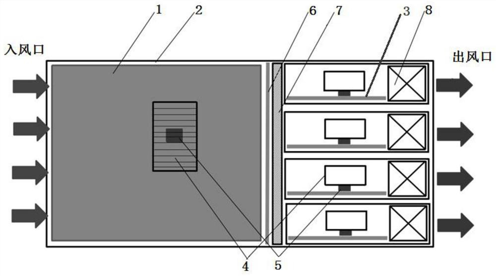
[0032] The present invention proposes a liquid cooling device with an orthogonal structure and a built-in cold source. The cold source can be arranged inside the device, which saves space, shortens the length of the pipeline for the working liquid to flow into the cold source, and further improves the cooling efficiency. The design utilizes existing fan systems to cool cold sources such as Figure 4 shown. Multiple cold sources 10 can also be provided, and each cold source is placed inside the exchange box 13 to dissipate heat for the corresponding exchange plate, further improving the design flexibility and heat dissipation efficiency of the heat dissipation device. The device also includes an air-cooled heat dissipation system ...


PUM


Abstract

The invention discloses a liquid cooling heat dissipation device of an orthogonal architecture subrack. The liquid cooling heat dissipation device comprises a line card with an orthogonal architecture, an exchange plate and a keel, and further comprises a liquid cooling heat dissipation device, wherein the liquid cooling heat dissipation device uses the keel as a carrier of a liquid-cooling fluidchannel and further used as a mounting carrier of the blind-mating liquid-cooling connector; a closed channel is arranged in the keel and serves as a liquid cooling fluid channel; a first cold plate is arranged on the exchange plate where the heating device is located, a closed channel is further arranged in the first cold plate to serve as a liquid cooling fluid channel, and the blind insertion liquid cooling connector is used for being connected with a port of the liquid cooling fluid channel located in the first cold plate and a port of the liquid cooling fluid channel located at the corresponding position of the keel. According to the liquid cooling heat dissipation device, the heat dissipation problem of a high-power-consumption device is solved, and safe, stable and efficient work ofelectronic equipment can be guaranteed.

Description

technical field [0001] The invention relates to a liquid cooling and heat dissipation device for electronic equipment, in particular to a liquid cooling and heat dissipation device with an orthogonal structure sub-box. Background technique [0002] With the continuous development of electronic technology, the power of electronic equipment systems is increasing, but the physical size is getting smaller and smaller, the heat flux density is also increasing sharply, and the risk of heat dissipation is increasing. Especially in a certain type of subrack equipment, the power consumption is increasing, and the traditional air-cooled heat dissipation challenges are becoming more and more serious, and the heat dissipation problem is prominent. Therefore, solving the heat dissipation of such equipment has become a difficulty and pain point in the industry. [0003] For this type of subrack equipment, the conventional structure adopts the form of direct ventilation, and the basic air...

Claims


Application Information

Patent Timeline
Patent Type & Authority Applications(China)
IPC IPC(8): H05K7/20
CPCH05K7/20136H05K7/20218
Inventor 朱旺法胡海聿马建峰
Owner 南京中新赛克科技有限责任公司
Why Eureka
Try Eureka