
Universal change-over switch capable of being rapidly replaced

A transfer switch, universal technology, applied in the direction of coupling device, fixed/insulated contact components, base/housing, etc., can solve the influence of normal operation of the reliable operation and maintenance personnel of the power grid, the slip wire wiring of the wiring pile head falls off, and the universal transfer switch is easily damaged To avoid unplanned power outages, reduce power loss, and save time and cost

Pending Publication Date: 2021-09-24
STATE GRID HUBEI ELECTRIC POWER CO XIAOGAN POWER SUPPLY CO
View PDF5 Cites 0 Cited by
  • Summary
  • Abstract
  • Description
  • Claims
  • Application Information

AI Technical Summary

Problems solved by technology

[0008] Substation operators need to operate the switch or knife switch through the universal transfer switch. The operating frequency is relatively high, and some intervals have a long operating life, which makes the universal transfer switch easy to damage, which affects the reliable operation of the power grid and the normal operation of maintenance personnel.
According to the investigation and statistics, the main reasons for the damage of the universal transfer switch are as follows: 1) The rotating part of the universal transfer switch is stuck to the rotating shaft and cannot rotate correctly; 2) The traffic light at the upper end of the universal transfer switch is damaged; 3) The rotating shaft is damaged; 4 ) The wiring pile head of the universal transfer switch slipped and the wiring fell off; 5) The spring connected to the rotating shaft of the universal transfer switch was damaged
Because the universal transfer switch is connected in series in the operation circuit, once the universal transfer switch fails, it must be replaced with a power outage. The replacement process has a narrow space, a long replacement time, and there is a hidden danger of accidentally touching the wires.

Method used


Image

  • Universal change-over switch capable of being rapidly replaced
  • Universal change-over switch capable of being rapidly replaced
  • Universal change-over switch capable of being rapidly replaced

Examples


Embodiment Construction

[0030] The present invention will be further described in detail below in conjunction with the accompanying drawings and specific embodiments.

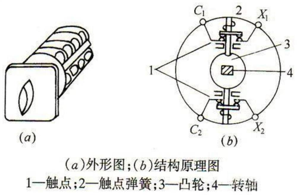
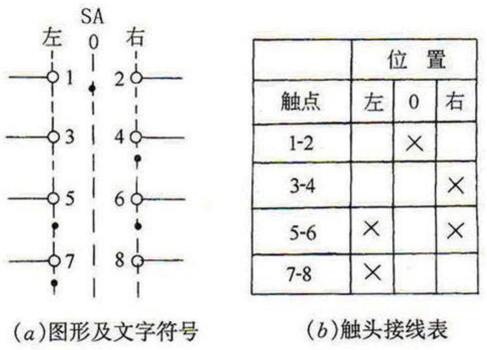
[0031] figure 1 with figure 2 For the existing universal changeover switch.

[0032] see Image 6 , the embodiment of the present invention includes the free-end aviation plug and the fixed-end aviation plug that are fitted together.

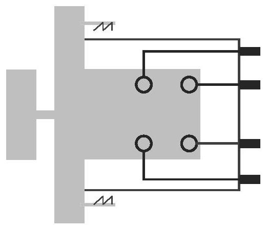
[0033] see image 3 with Figure 4 , the free-end aviation plug includes auxiliary switches, shells, connectors, and sleeves;

[0034] The auxiliary switch selects the LW12 series self-resetting type, the heating current is 16A, the insulation voltage is 690V, and the applicable capacity is below 5.5kW; after the handle is released, the handle of the self-resetting auxiliary switch automatically returns to the original position, with large heating current and large applicable capacity.

[0035] The shell is a hollow cylinder with one end open, the outer diameter of the bottom surface is 40mm*40mm...


PUM


Abstract

The invention provides a universal change-over switch capable of being rapidly replaced, an existing universal change-over switch is improved into an aviation plug type universal change-over switch by adopting a mode of additionally installing the shell, and the purpose that the universal change-over switch is safely, rapidly and reliably replaced by plugging and unplugging the male head and the female head under the condition that normal power supply is not affected is achieved. The switch is convenient and visual, is high in safety and reliability, and is not likely to cause DC grounding or short circuit. According to the invention, human input is reduced, the fault processing efficiency is higher, the workload of workers is reduced, the power supply reliability of a power grid is ensured, and safe and stable operation of the power grid is facilitated.

Description

technical field [0001] The invention belongs to the technical field of electrical connectors, and in particular relates to a quickly replaceable universal transfer switch. Background technique [0002] The universal transfer switch is a multi-gear, multi-stage, multi-circuit master electrical appliance. When the operating handle is rotated, the cam inside the switch is driven to rotate, so that the contacts are closed or disconnected in a prescribed order. It is mainly suitable for AC 50Hz, rated working voltage 380V and below, DC voltage 220V and below, rated current 160A electrical circuit, the universal switch is mainly used for the conversion of various control circuits, commutation measurement control of voltmeters and ammeters, and distribution device circuits. Conversion and remote control, etc., are often used in substations to open and close circuit breakers (switches), and operate remotely / locally. [0003] The universal transfer switch is a multi-circuit control ...

Claims


Application Information

Patent Timeline
Patent Type & Authority Applications(China)
IPC IPC(8): H01R31/06H01R13/46H01R13/42
CPCH01R31/06H01R13/46H01R13/42
Inventor 曹冲肖洒黄晓舟王晓新聂力黄乔宇张茜曹显刘亮杨帆张尖兵代维谦杨耿琦胡康杨鑫张莉周婧娴钟思杨蔡盛杨峰胡焕张万
Owner STATE GRID HUBEI ELECTRIC POWER CO XIAOGAN POWER SUPPLY CO
Learn More