Welding machine for making and supporting columns of steel structure of bus station

A technology for supporting columns and welding machines, which is applied in the field of manufacturing welding machinery for steel structure supporting columns of bus stops, can solve the problems of low connection tightness, increased service life, and easy deflection of the base, etc., and achieves improved connection tightness, improved Welding quality, the effect of improving the stability

Active Publication Date: 2021-10-29
江苏久泰智能科技有限公司
View PDF5 Cites 0 Cited by
  • Summary
  • Abstract
  • Description
  • Claims
  • Application Information

AI Technical Summary

Problems solved by technology

[0003] The bus platform is composed of columns, ceilings, light boxes, seats, dustbins, line signs, etc., and the columns are composed of columns and bases. The most basic function of the columns is to bear weight. The materials of the columns are also divided into stainless steel and galvanized sheets. And aluminum profiles, the surface can be sprayed and painted to increase the service life. The common shapes of the columns include square, rectangular, cylindrical, etc.; take the production of square columns as an example: first fix the square column, and then use the existing welding equipment Weld the square column and the base, and then transport the square column to the installation point of the bus platform for assembly with other structures. The base and the ground are connected by studs, but the square column and the base are welded. The following problems will occur in the process: the overall stability of the square column under the action of the simple clamping structure is low, so that the square column is more prone to deflection during welding with the base, and in many cases, the alignment will be ignored. The base is treated with bottom support, so that the base is also prone to deflection during welding, and the connection between the base and the square column is relatively tight, which affects the welding effect between the two

Method used


Image

  • Welding machine for making and supporting columns of steel structure of bus station
  • Welding machine for making and supporting columns of steel structure of bus station
  • Welding machine for making and supporting columns of steel structure of bus station

Examples


Embodiment Construction

[0032] Next, the technical solutions in the embodiments of the present invention will be described in connection with the drawings of the embodiments of the present invention, and it is understood that the described embodiments are merely the embodiments of the present invention, not all of the embodiments. Based on the embodiments of the present invention, all other embodiments obtained by those of ordinary skill in the art are in the range of the present invention without making creative labor premise.

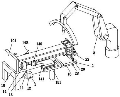
[0033] See figure 1 with Figure 8 A bus station steel structure support column produces welding machinery, including clamping mechanism 1, mobility mechanism 2, and welding machine 3, said clamping mechanism 1, on the ground, the right end of the clamp mechanism 1 is provided with mobility Mechanism 2, the right side of the clamping mechanism 1 is arranged with a welding machine 3, and the welding machine 3 is placed on the ground.

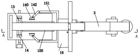
[0034] See figure 1 , figure 2 with Figure 8 ...


PUM


Abstract

The invention relates to the field of steel structure welding of bus stops, in particular to a welding machine for making steel structure support columns of bus stops, including a clamping mechanism, an abutment mechanism and a welding machine. The clamping mechanism is placed on the ground, and the clamping mechanism An abutment mechanism is provided at the right end of the clamping mechanism, and a welding machine is arranged on the right side of the clamping mechanism, and the welding machine is placed on the ground. The invention adopts the design concept of multiple limit positions, thereby improving the stability of the square column in the clamping state. The resisting mechanism designed in the present invention can support the bottom of the base, thereby avoiding the deflection of the base during welding, and at the same time, the resisting mechanism can exert a certain resisting force on the base The connection tightness between the base and the square column is improved, thereby improving the welding quality between the base and the square column.

Description

Technical field [0001] The present invention relates to the field of non-bus structural welding fields, and in particular, to a bus station steel structure support column production welding machinery. Background technique [0002] The bus stop is a public facility specializing in the construction of a city waiting for the city; the bus station is multi-module assembly to the mounting point for overall assembly, and the integral molding of the bus platform is used in the mounting method. [0003] The bus stop consists of a column, a ceiling, a light box, a seat, a trash. The line indicates, and the column is composed of the column and the base. The most basic effect of the column is to load weight, the material of the column is also divided into stainless steel, galvanized plate And aluminum profiles, surfaces can be sprayed, painted, increased useful, and the common shapes of the column include square, rectangular, cylindrical, etc .; as an example of the square column: first, th...

Claims


Application Information

Patent Timeline
Patent Type & Authority Patents(China)
IPC IPC(8): B23K37/00B23K37/02B23K37/04
CPCB23K37/00B23K37/02B23K37/0443B23K2103/04
Inventor 史瑞
Owner 江苏久泰智能科技有限公司
Why Eureka
Try Eureka