A parallel type three-axis linear robot

A robot and parallel technology, applied in manipulators, program-controlled manipulators, manufacturing tools, etc., can solve the problems of short working stroke, long branch link mechanism, insufficient motion stability, etc., and achieve increased working stroke and large working stroke. , space saving effect

Pending Publication Date: 2021-09-28
蓝兆杰
View PDF9 Cites 0 Cited by
  • Summary
  • Abstract
  • Description
  • Claims
  • Application Information

AI Technical Summary

Problems solved by technology

[0012] The technical problem to be solved by the present invention is to provide a parallel three-axis linear robot to solve the problem of the long length of the branch link mechanism of the existing triangular robot, the existing right-angle parallel robot and the existing three-degree-of-freedom parallel mechanism. It causes problems such as short working stroke and insufficient motion stability, and at the same time solves the problem that the existing and existing double five-bar mechanism-driven planar parallel mechanism cannot provide the driving platform to generate three-dimensional space motion functions, etc.

Method used


Image

  • A parallel type three-axis linear robot
  • A parallel type three-axis linear robot
  • A parallel type three-axis linear robot

Examples


Embodiment Construction

[0090] In the following, the technical means adopted by the present invention to achieve the intended purpose of the invention will be further described in conjunction with the accompanying drawings and preferred embodiments of the present invention.

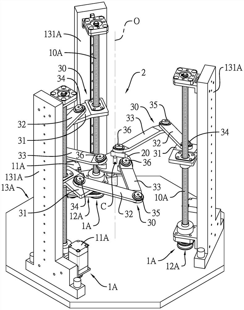
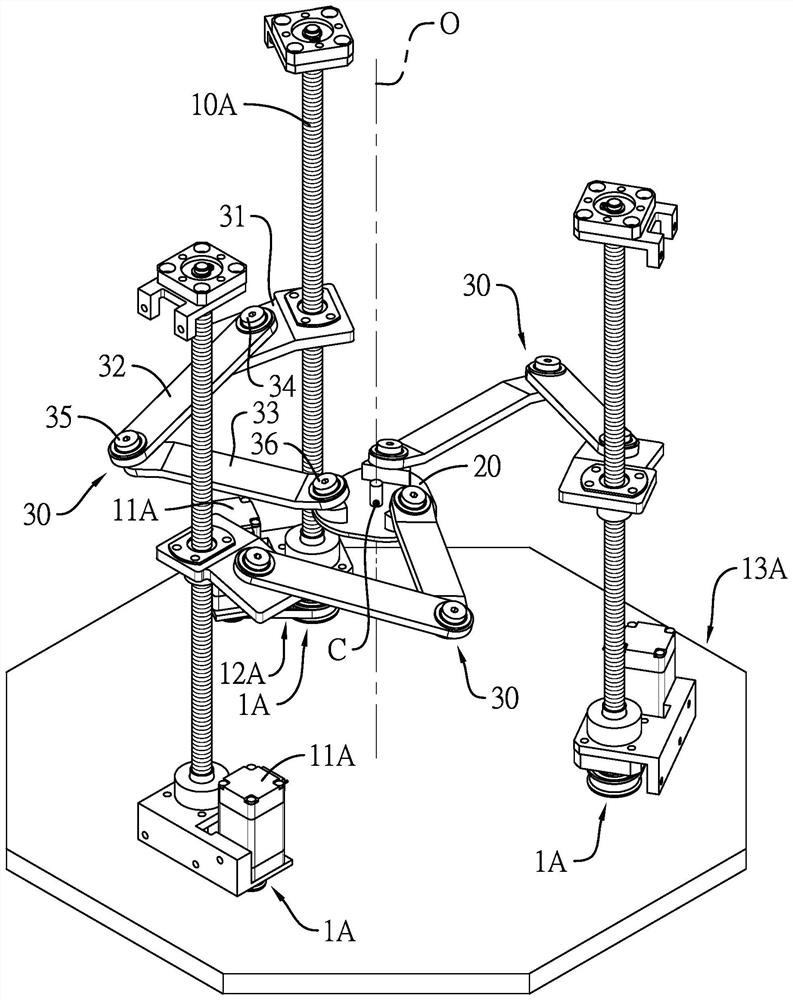
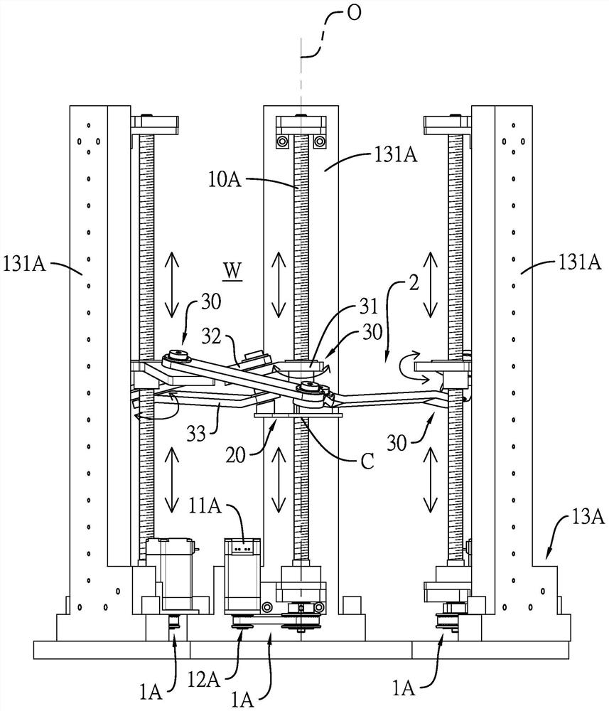
[0091] like figure 1 , Figure 5 and Figure 10 As shown, it discloses three preferred embodiments of the parallel three-axis linear robot of the present invention. As can be seen from these drawings, the parallel three-axis linear robot defines a workspace W (workspace) and through the work A central axis O of the geometric center of the section W includes three drivers 1A, 1B, 1C and a motion mechanism 2 .

[0092] like figure 1 , Figure 5 and Figure 10 As shown, the three drivers 1A, 1B, and 1C are distributed and disposed on the periphery of the central axis O, and the three drivers 1A, 1B, and 1C input driving forces in a linear or rotational manner. The three drivers 1A, 1B, 1C can at least figure 1 , Figure 5 a...


PUM


Abstract

The invention relates to a parallel type three-axis linear robot. The parallel type three-axis linear robot comprises three drivers located on the periphery of a central axis and a movement mechanism. The movement mechanism comprises a three-connecting-rod set which is rotationally symmetrical relative to the central axis and an end effector which is connected with the three-connecting-rod set in parallel. Each connecting rod set is driven by a driver in a linear or rotating manner, so that the end effector can linearly move in a three-dimensional space; each connecting rod set comprises a first connecting rod, a second connecting rod and a third connecting rod which are sequentially connected in series, wherein the third connecting rod is pivoted to the end effector; the first rotating joint, the second rotating joint and the third rotating joint are respectively pivoted among the first connecting rod, the second connecting rod, and the third connecting rod; included angles between the first to third rotary joints and an imaginary plane perpendicular to the central axis are acute angles; the first center distance between the first rotating joint and the second rotating joint is equal to the second center distance between the second rotating joint and the third rotating joint, so that the overall height of the movement mechanism can be reduced, the working stroke is increased, and the movement stability is improved.

Description

technical field [0001] The invention relates to a three-axis linear robot, in particular to a parallel three-axis linear robot that can be widely used in the fields of robots and other automatic machinery. Background technique [0002] The currently known parallel three-axis linear motion robot is generally disclosed in "Device for the movement and positioning of anelement in space" (Device for the movement and positioning of anelement in space) disclosed in U.S. US4976582 patent, " Cartesian parallel manipulators” (Cartesian parallel manipulators), and the “structure-adjustable three-degree-of-freedom parallel mechanism” disclosed in the Chinese patent CN105150199A. in: [0003] The "device for moving and positioning components in space" disclosed by the U.S. patent US4976582 is generally referred to as a delta robot (Delta robot). The device is used as the output end, and each branch linkage mechanism is driven by a set of drive components. Each branch linkage mechanism ...

Claims


Application Information

Patent Timeline
Patent Type & Authority Applications(China)
IPC IPC(8): B25J9/00B25J9/12B25J9/16
CPCB25J9/0045B25J9/12B25J9/1607B25J9/0036B25J9/0048B25J17/0283
Inventor 蓝兆杰
Owner 蓝兆杰
Why Eureka
Try Eureka