
Fabricated slab culvert main body structure and construction method thereof

A technology of the main structure and construction method, which is applied in the direction of buildings and road bottom layers, can solve the problems of uneven construction and maintenance quality and low construction efficiency of slabs and culverts, and achieve the goals of shortening the construction period, less maintenance water, and improving the working environment Effect

Inactive Publication Date: 2021-09-28
刘凯
View PDF2 Cites 0 Cited by
  • Summary
  • Abstract
  • Description
  • Claims
  • Application Information

AI Technical Summary

Problems solved by technology

[0004] The purpose of the present invention is to provide a main structure of an assembled slab culvert to solve the problems of low construction efficiency and uneven construction and maintenance quality of the existing slab culvert

Method used


Image

  • Fabricated slab culvert main body structure and construction method thereof
  • Fabricated slab culvert main body structure and construction method thereof
  • Fabricated slab culvert main body structure and construction method thereof

Examples


Embodiment 1

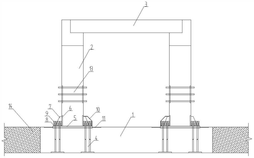
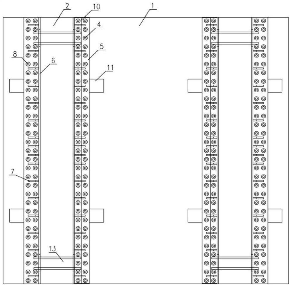
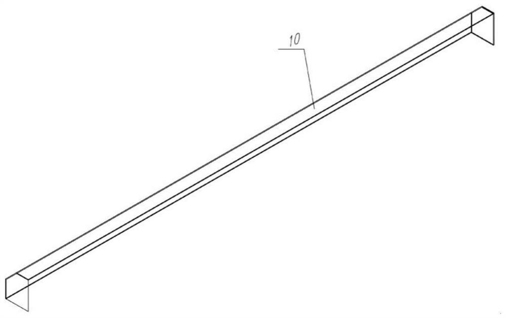
[0048] Such as Figure 1 to Figure 4 As shown, the main structure of the assembled cover plate of this embodiment includes a prefabricated base plate 1, a prefabricated platform body 2 and a prefabricated cover plate 3, anchor bolts 4 are pre-embedded in the base plate 1, and a base frame steel plate 5 is provided at the bottom of the platform body 2 , base side steel plate 6, stiffening steel plate 7 and rectangular threaded steel bar 19, base frame steel plate 5 and anchor bolt 4 are connected by double-layer nut 8, platform body 2 is provided with platform body embedded bolt 13 for installing spreader, cover The plate 3 is arranged on the platform cap at the upper end of the platform body 2, a steel glue layer is provided under the base frame steel plate 5, a stainless steel box cover 10 is provided on the water side of the bottom of the platform body 2, and the base frame steel plate 5 and The base side steel plate 6 is accommodated in the stainless steel box cover 10 . T...

Embodiment 2

[0050] Part of the steps are conventional means, and will not be repeated here. The following are the main steps of the present invention.

[0051] Such as Figure 5 As shown, the cover plate is installed to cover the bottom plate 1, the backfill material 14 on one side of the bottom plate 1 is compacted, the temporary support 151 of the platform body is installed, and the guide frame 12 is installed on the welding platform body; The height is about 13cm, and the self-weight does not exceed 25kg. Perforated lugs are arranged on the side of the top plate, and the double-layer temporary support is fixed vertically by bolts. This facilitates the handling and installation of the platform body temporary support 151 .

[0052] Such as Figure 6 and Figure 7 As shown, the temporary support 152 of the jack is installed, and the vertical space is fixed with bolts, and then the three-dimensional jack 18 is installed, and the three-dimensional jack 18 vertically tightens the cantilev...


PUM


Abstract

The invention discloses an assembly type slab culvert main body structure which comprises a prefabricated bottom plate, a prefabricated platform body and a prefabricated cover plate, anchor bolts are pre-buried in the bottom plate, a base framework steel plate, base side steel plates, stiffening steel plates and rectangular twisted steel are arranged at the bottom of the platform body, the base framework steel plate is connected with the anchor bolts through double-layer nuts, the platform body is provided with an embedded bolt used for installing a lifting appliance, the cover plate is arranged on a platform cap at the upper end of the platform body, a sticky steel glue layer is arranged below the base framework steel plate, a stainless steel box cover is arranged on the side, close to water, of the bottom of the platform body, and the base framework steel plate on the side close to water and the base side steel plate are contained in the stainless steel box cover. The problems that an existing slab culvert is low in construction efficiency and uneven in construction and maintenance quality are solved.

Description

technical field [0001] The invention relates to the field of slab culvert construction technology, in particular to a main structure of an assembled slab culvert and a construction method thereof. Background technique [0002] In recent years, with the continuous acceleration of my country's highway traffic construction process, more and more highway projects have begun to enter the implementation stage. In view of the problems of traditional cast-in-place slab and culvert structure construction that have a large impact on the environment, long construction period, high carbon emissions, and uneven on-site maintenance quality, starting from technological advancement, applicability, reliability, safety and economy, It is an innovative work with economic, social and ecological benefits to study the new technology for the design and construction of the main structure of the prefabricated slab culvert suitable for the construction of highway traffic in our country. Traditional ...

Claims


Application Information

Patent Timeline
Patent Type & Authority Applications(China)
IPC IPC(8): E01F5/00
CPCE01F5/005
Inventor 刘凯谌意雄李敏峰李球世张磊黎强
Owner 刘凯
Learn More