Joint linkage control structure and laboratory central fresh air control system

A technology of linkage control and control system, applied in ventilation system, space heating and ventilation control input, air conditioning system, etc., can solve air pollution, human injury and other problems, achieve uniform exhaust, strong practicability, and novel design. Effect

Pending Publication Date: 2021-09-28
兰州凯博莱特实验室系统工程有限公司
0 Cites 0 Cited by

AI-Extracted Technical Summary

Problems solved by technology

[0003] In the laboratory, due to the need for work, it is often necessary to carry out relatively dangerous experiments, resulting in a certain amount of toxic and harmful gases, which will cause harm to the human body if they accumulate in the laboratory for a long time. The trad...

Method used

In an embodiment of the present invention, when in use, after the gas poisonous substance in the laboratory is detected by the detector 2, the stepper motor 3 is driven to work, and the stepper motor 3 drives the The adjustment assembly works to make the telescopic plate 7 move, and the telescopic plate 7 drives the No. 1 gear 14 to move, and a buffer assemb...

Abstract

The invention relates to a joint linkage control structure and a laboratory central fresh air control system. The joint linkage control structure comprises a fresh air treatment cabinet, a detector and a stepping motor, wherein the detector and the stepping motor are arranged on the fresh air treatment cabinet, the stepping motor is connected with an adjusting assembly, the adjusting assembly is connected with a telescopic plate, the telescopic plate matches a fixing plate, the telescopic plate is connected with a moving block by means of a buffering assembly, a first gear is arranged on the moving block, and a driving piece is further arranged on the telescopic plate. The laboratory central fresh air control system comprises a motor, wherein an output shaft of the motor is connected with a bevel gear set, the bevel gear set is connected with a second gear, the motor is further connected with a transmission assembly, the transmission assembly is connected with a fan, the output shaft of the motor is further connected with a forward and reverse rotation assembly, the forward and reverse rotation assembly is connected with a steel wire, the steel wire is provided with an air outlet, the air outlet is connected with a guide assembly, and the air outlet is connected with an exhaust outlet of the fan. The structure and the system are novel in design, simple in structure and high in practicability.

Application Domain

Technology Topic

Image

  • Joint linkage control structure and laboratory central fresh air control system
  • Joint linkage control structure and laboratory central fresh air control system
  • Joint linkage control structure and laboratory central fresh air control system

Examples

  • Experimental program(1)

Example Embodiment

[0022] Next, the technical solutions in the embodiments of the present invention will be apparent from the embodiment of the present invention, and it is clearly described, and it is understood that the described embodiments are merely embodiments of the present invention, not all of the embodiments. Based on the embodiments of the present invention, there are all other embodiments obtained without making creative labor without making creative labor premises.
[0023] Further, the elements in the present invention are referred to as "fixed to" or "set to" another element, which can be directly in another element or may also exist in the hidden components. When a component is considered to be "connected" another element, it may be directly connected to another element or may always exist in the center element. The term "vertical", "horizontal", "left", "right", "left", "right", "left", "right", and similar expressions are not shown, as unique embodiments.
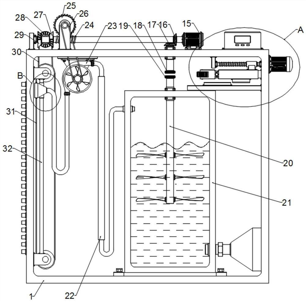
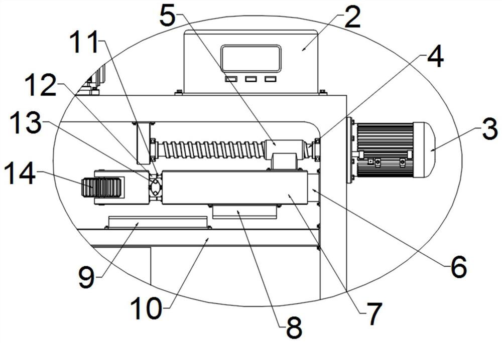
[0024] See Figure 1 ~ 4 In the embodiment of the present invention, a joint linkage control structure includes a new wind treatment cabinet 1 and a detector 2 disposed on the new wind treatment cabinet 1, and a stepping motor 3, the detector 2. An electrically connected to the stepper motor 3, the stepper motor 3 outputs an adjustment assembly disposed on the new wind treatment cabinet 1, the adjustment assembly to connect to a telescopic plate 7, and the telescopic The plate 7 is in the interior and is attached to the fixed plate 6 disposed on the new wind treatment cabinet 1, and one end of the telescopic plate 7 is connected by a buffer assembly, and the moving block is rotated and sets a 1 gear 14. An active sheet 8 is further provided on the stretch plate 7, the active sheet 8 adapted to a fixed block 9 on the casing 10 of the new wind treatment cabinet 1.
[0025] In the embodiment of the present invention, when the detector 2 detects the gas toxic substance in the laboratory, the stepper motor 3 is driven, the stepper motor 3 drives the adjustment assembly. Working, the telescopic plate 7 moves, the telescopic plate 7 drives a first to gear 14, and a cushioning assembly prevents the structure of the first gear 14 from being destroyed.
[0026] As an embodiment of the present invention, the adjustment assembly includes a rod 4 having an output shaft of the stepper motor 3 and rotatably disposed on the new wind treatment cabinet 1, and a thread with the thread of the rod 4 The sleeve 5, the threaded sleeve 5 connects the telescopic plate 7 by the connecting block.
[0027] In the embodiment of the present invention, when the stepper motor 3 is rotated, the threaded sleeve 5 threaded with the rod 4 is rotated when the stepper motor 3 is rotated such that the threaded sleeve 5 of the rod 4 is in the shaft of the rod 4. Movement in the direction, driving the telescopic plate 7, the telescopic plate 7 drives the active sheet 8 to bind to the fixing block 9 such that the heater 22 is energized while the first gear 14 and the The second gear 18 and the three gear 19 mesh, driving the stirring rod 20 to rotate, so that the air is sufficiently mixed with the adsorption.
[0028] As an embodiment of the present invention, the buffer assembly includes a fixing tub 11 fixed to the stretch plate 7 and a slide bucket 12 adapted to the fixing tub 11 and one end fixed to the moving block 12 And the torsion spring 13 of the moving block and the telescopic plate 7 is connected.
[0029] In the embodiment of the present invention, when the telescopic plate 7 is used, the first gear 14 is engaged with the second gear 18 and the three gear 19, by providing a torsion spring 13 to avoid because The structure of the first gear 14 and the adjustment assembly is destroyed.
[0030]As an embodiment of the present invention, a laboratory central new wind control system includes the joint linkage control structure, the laboratory central new wind control system further includes fixed settings. In the new wind treatment cabinet 1, the motor 15 outputs the shaft connection in the new wind treatment cabinet 1, the cone gear set, which is arranged in the new wind treatment cabinet. 2 gear 18, the second gear 18 is adapted to the first gear 14;
[0031] The motor 15 output shaft is also connected to a transmission assembly disposed on the new wind treatment cabinet 1, which is connected to a fan 23 in the new wind treatment cabinet 1 through a single belt 26, and the air engine 23 The venting tube is disposed in the mixing tank 21 in the new wind treatment cabinet through the connecting pipe connection, and the connecting tube is provided with a heater 22 and the heater 22 electrically connected to the fixed block 9, the mixing box 21 The air outlet is connected by a one-way valve, and the mixing tank 21 is further rotated, and one end of the stirrer rod 20 is connected to the third gear 19, the three gear 19 and the first gear 14 adaptation. ;
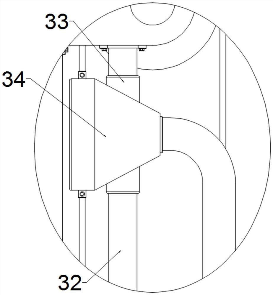
[0032] The output shaft of the motor 15 is also connected to a positive inversion assembly disposed on the new wind treatment cabinet 1, and the positive inversion assembly is provided in the new wind wire 31 in the new wind treatment cabinet 1 through the second belt 30. The wire wire 31 is fixedly provided with a wind port 34 that is connected to the guide assembly disposed within the new wind treatment cabinet and the air port 34 is connected to the vent 23.
[0033] In the embodiment of the present invention, when used, the motor 15 is driven, the motor 15 drives the fan 23 by the transmission assembly, and the air in the laboratory into the mixing tank 21, The mixing tank 21 is attached to a liquid having a toxic substance, and the air is discharged by the blower 23 after the mixing tank 21 is absorbed, while the motor 15 is discharged, while the motor 15 drives the wire wire 31 by the positive inverting assembly. Dressing, driving the air outlet 34 to perform up and down reciprocating motion under the action of the guiding assembly, achieve uniform exhaust gas, when the detector 2 detects that the gas toxic substance in the laboratory is over the range, drive the drive The stepper motor 3 operates, the stepper motor 3 operates the adjustment assembly such that the telescopic plate 7 moves, the telescopic plate 7 drives the first gear 14 and the second gear 18 and the three The gear 19 is engaged, and the stirring rod 20 is rotated so that the gas entering the mixing tank 21 can be better mixed with the adsorbent to achieve a better adsorption effect, while the heater 22 operates, in the air Water vapor evaporation, avoiding the gaseous humidity of the discharge, simple structure, and strong practicality.
[0034] As an embodiment of the present invention, the cone gear set includes a first taper gear 16 disposed on the output shaft of the motor 15 and engages the first taper gear 16 and is rotated in the new wind treatment cabinet 1. The second taper gear 17, the second taper gear 17 connects the second gear 18.
[0035] In the embodiment of the present invention, when the motor 15 is rotated, the first taper gear 16 is rotated such that the second cone 17 meshing the first cone gear 16 is rotated, thereby driving the The mixer rod 20 is rotated.
[0036] As an embodiment of the present invention, the transmission assembly includes a worm 24 outputting a shaft connection with the motor 15 and is rotatably disposed on the new wind treatment cabinet and engaged with the worm 24 and is rotated in the new wind. The worm gear 25 on the treatment cabinet 1, the worm wheel 25 connects the fan 23 by the first belt 26.
[0037] In the embodiment of the present invention, when the motor 15 is rotated, the worm 24 is rotated so that the worm wheel 25 meshed with the worm 24 rotates, and the worm wheel 25 is driven by the first belt 26. The fan 23 is rotated, and the air in the laboratory is pumped into the mixing tank 21.
[0038] As an embodiment of the present invention, the positive inversion assembly includes a one-level incomplete cone 27 and No. 2 incomplete cone gear 29 and No. 2 incomplete cone 29 and the No. 1 incomplete cone with the first number. The gear 27 and the No. 2 incomplete cone gear 29 are adapted to the fully cone gear 28, the fully cone gear 28 to connect the steel wire 31 by the second belt 30.
[0039] In an embodiment of the present invention, when the motor 15 is rotated, the one is not fully cone gear 27 and the second incomplete cone gear 29 are driven, the one is incomplete cone. The gear 27 and the second incomplete cone gear 29 have a tooth part without teeth, and when the portion of the orthodox gear 27 is engaged with the full cone gear 28, the second is incomplete cone gear 29 The no tooth is adapted to the fully cone gear 28, realization, when the No. 2 incomplete cone gear 29 is engaged with the full cone gear 28, when the No. 1 incomplete cone 27 no tooth The part is adapted to the fully cone gear 28, and it is reversed.
[0040] As an embodiment of the present invention, the guide assembly includes a guide rod 32 fixed within the new wind treatment cabinet and a sliding sleeve 33 that slides on the guide rod 32, the sliding sleeve 33 Fixed with the exhaust port 34.
[0041] In the embodiment of the present invention, when the positive inverting assembly is used, the wire wire 31 is driven up and down, and the wind tower 34 is driven up and down, and the guide rod 32 and the setting are used. The sliding sleeve 33 on the guide rod 32 avoids swinging of the exhaust port 34 such that the air direction is changed.
[0042] It is apparent to those skilled in the art that the present invention is not limited to the details of the exemplary embodiments, and the present invention can be implemented in other specific forms without departing from the spirit or essential characteristics of the present invention. Therefore, in any case, it should be regarded as an exemplary, and non-limiting, and the scope of the invention is defined by the appended claims. Therefore, it is intended to fall in accordance with the claims All variations in the meaning and range of equivalents are included in the present invention. Any reference numerals in the claims should not be regarded as the claims.
[0043] In addition, it should be understood that although this specification describes in accordance with an embodiment, it is not to include only one independent technical solution. The description of the specification is simply, and those skilled in the art should use the specification as a whole. The technical solutions in each embodiment may also be appropriately combined to form another embodiments which will be appreciated by those skilled in the art.

PUM

no PUM

Description & Claims & Application Information

We can also present the details of the Description, Claims and Application information to help users get a comprehensive understanding of the technical details of the patent, such as background art, summary of invention, brief description of drawings, description of embodiments, and other original content. On the other hand, users can also determine the specific scope of protection of the technology through the list of claims; as well as understand the changes in the life cycle of the technology with the presentation of the patent timeline. Login to view more.

Similar technology patents

Classification and recommendation of technical efficacy words

  • Innovative design
  • Uniform exhaust

Catheter with bendable tip

Owner:BIOSENSE WEBSTER INC

Efficient broadband switching-mode amplifier

ActiveUS20050083122A1Innovative designPresent inventionPush-pull amplifiersPhase-splittersAudio power amplifierBroadband amplifiers
Owner:RAYTHEON CO

Curing chamber with improved air outlet

PendingCN108682783AUniform exhaustImprove uniformityElectrode manufacturing processesAirflowElectronic shutter
Owner:TIANNENG BATTERY WUHU

Multi-curved glass forming method and forming device

InactiveCN110963677AUniform exhaustNot easily deformedGlass reforming apparatusMoulding deviceGlass forming
Owner:SHENZHEN JINGJIANG YUNCHUANG TECH CO LTD

Targeted ventilation device for animal house

PendingCN113692972AReduce cooling costsUniform exhaustAnimal housingAnimal scienceEngineering
Owner:山东高烽畜牧科技有限公司
Why Eureka
Try Eureka