Switch with bottom provided with cavity for accommodating electronic circuit board

A technology for electronic circuit boards and switches, applied in electrical switches, circuits, protection switches, etc., can solve the problems of complicated maintenance work, reduced convection heat dissipation, reduced heat dissipation effect, and reduced reliability.

Pending Publication Date: 2021-09-28
TIANJIN SVRUI INTELLIGENT ELECTRICAL CO LTD
View PDF0 Cites 0 Cited by
  • Summary
  • Abstract
  • Description
  • Claims
  • Application Information

AI Technical Summary

Problems solved by technology

The increase of equipment increases the complexity of the low-voltage power distribution system, and it is not easy to share the functions of similar functional modules, a series of problems such as repeated construction, non-repetitive equipment utilization, reduced reliability, and complicated maintenance work.
[0003] Reduce project costs, streamline equipment, improve the shar

Method used


Image

  • Switch with bottom provided with cavity for accommodating electronic circuit board
  • Switch with bottom provided with cavity for accommodating electronic circuit board
  • Switch with bottom provided with cavity for accommodating electronic circuit board

Examples


no. 1 example

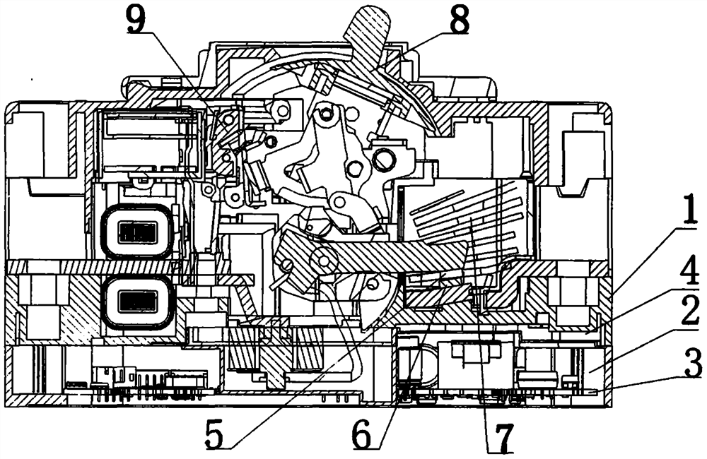
[0036] Such as figure 1 , which is a schematic diagram of a switch with a cavity at the bottom for accommodating an electronic circuit board. The switch includes an insulating case 1, a cavity 2, an electronic circuit board 3, a moving contact 5, a static contact 6, and an arc extinguishing chamber 7 , operating mechanism 8, fault protection release 9, the electronic circuit board 3 is arranged in the cavity 2, the moving contact 5, static contact 6, arc extinguishing chamber 7, operating mechanism 8 and fault protection The tripper 9 is arranged in the insulating casing 1, and the insulating casing 1 and the cavity 2 are arranged separately. At least one air interlayer 4 is arranged between the insulating housing 1 and the cavity 2, and the air interlayer 4 prevents the electronic components on the electronic circuit board 3 from being in direct contact with relatively high-temperature surfaces, Reduce the level of conduction and heat dissipation, prevent heat from being dir...

no. 2 example

[0045] The second embodiment is based on the first embodiment, so only the differences from the first embodiment are described in the following description.

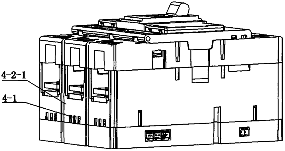
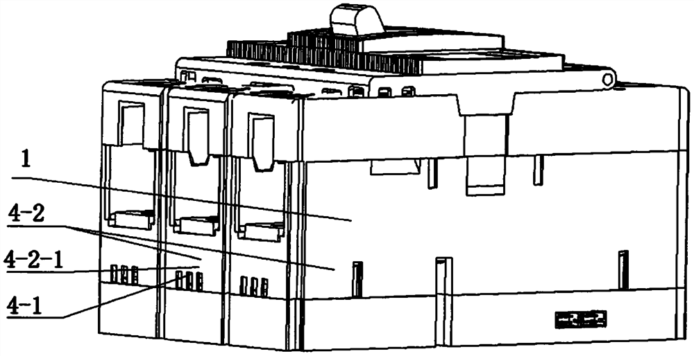
[0046] Such as Figure 9 , the air convection hole 4-1 is arranged on any at least two surfaces 4-2 that can form convection around the switch, and the side 4-2 includes side A, side B, side C, and side D, specifically The combination can be on two sides: side A, side B; side A, side C; side A, side D; side B, side C; side B, side D; side C, side D. On three sides: side A, side B, side C; side A, side B, side D; side B, side C, side D. On four sides: side A, side B, side C, side D. The specific settings are selected and determined according to heat dissipation requirements.

no. 3 example

[0048] The third embodiment is an embodiment based on the first embodiment and the second embodiment, so only the differences from the first embodiment and the second embodiment are described in the following description.

[0049] Such as Figure 10 As shown, in this embodiment, the insulating shell 1 and the cavity 2 are integrated, that is, the cavity 2 is set in the insulating shell 1, and others are the same as those of the first embodiment or the second embodiment Same, no more details here.


PUM


Abstract

The invention discloses a switch with the bottom provided with a cavity for accommodating an electronic circuit board, wherein the switch comprises an insulating shell (1), a cavity (2), an electronic circuit board (3), a moving contact (5), a static contact (6), an arc extinguish chamber (7), an operating mechanism (8) and a fault protection release (9); and an air interlayer (4) is arranged between the insulating shell (1) and the cavity (2) and is provided with an air convection hole (4-1); and the air interlayer (4) obstructs direct conduction of heat and realizes natural air convection heat dissipation and cooling. According to the switch, the temperature of the cavity can be effectively reduced, and the service life of electronic components in the electronic circuit board in the cavity is prolonged.

Description

technical field [0001] The invention relates to the field of low-voltage electrical appliances, in particular to a switch with a cavity at the bottom for accommodating an electronic circuit board. Background technique [0002] As the State Grid continues to promote the construction of the ubiquitous power Internet of Things, various products in the power system are continuously upgraded and upgraded. In addition to maintaining the original protection functions such as overload and short circuit, the switch also adds functions such as electrical quantity data detection, communication, and data display. . In order to realize these new functions, it is necessary to add communication modules, more electronic controllers, display modules, high-precision and wide-range current acquisition modules, and voltage acquisition modules. The addition of various modules makes the inner cavity size of the switch unable to accommodate so many Modules, peripheral devices such as backpack swi...

Claims


Application Information

Patent Timeline
IPC IPC(8): H01H71/02H01H71/04H01H9/52
CPCH01H71/02H01H71/0207H01H71/04H01H9/52
Inventor 南寅朱金保陈斌谷春雷连云飞于雷章龙施谦吕毅华张炎
Owner TIANJIN SVRUI INTELLIGENT ELECTRICAL CO LTD
Why Eureka
Try Eureka