Binocular holder of visible light camera and infrared thermal imaging camera
An infrared thermal imaging and camera technology, which is applied in the field of cameras, can solve the problems that the main box of the camera does not have the heat dissipation function, the damage of components, and the reduction of the service life of the camera.
- Summary
- Abstract
- Description
- Claims
- Application Information
AI Technical Summary
Problems solved by technology
Method used
Image

Examples
Embodiment 1
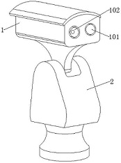
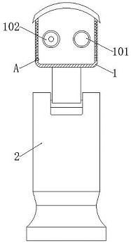
[0037] See Figure 1-3 In the embodiment of the present invention, a visible light camera and an infrared thermal imaging camera comprise a camera main box 1, a visible light camera 101, an infrared thermal imaging camera 102, and a motor vehicle 2, characterized in that the camera main box 1 The inner wall inner wall inner wall in the longitudinal side of the inner wall is embedded in a vertical direction or the like, and a heat dissipation assembly 3 which can dissipate heat;
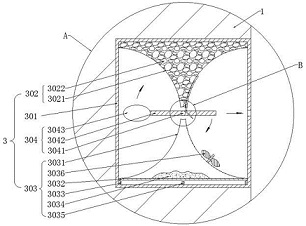
[0038] Each set of heat dissipating assemblies 3 includes a metal case 301 that stores a cooling material of the storage assembly 302, which can generate cold air refrigeration assembly 303 and movable assembly 304 that can be freely active with temperature.
[0039] In the embodiment of the present invention, each metal case 301 has a long square shape in the interior, and each metal case 301 is copper, and the central portion of each metal shell 301 has a cold air outlet, each metal. Both the top side of...
Embodiment 2
[0043] See Figure 3-5 The embodiments of the present invention are distinguishable relative to Example 1 in that each group of storage assemblies 302 includes an upper groove 3021 and a water 3022.
[0044] In the embodiment of the present invention, each of the upper grooves 3021 is narrow in a longitudinal section, and there is a reverse shape of the inner hollow and the left and right sides, each of which is pre-installed in each of the upper grooves 3021. Waste water 3022, the bottom of each upper groove 3021 is opened with a clear water exit;
[0045] Here, the appearance of the upper groove 3021 is set to a longitudinal section of a longitudinal section, and the inverted tract shape having an exterior in the interior and the left and right sides is to be opened to the clear water outlet of the clean water 3022 in which it is stored. At the time of flow, it can be transmitted to the refrigeration assembly 303 along the moving component 304 to trigger the cooling, and the radi...
Embodiment 3
[0051] See Figure 3-4 , Figure 6-7 The embodiments of the present invention are distinguishable relative to Example 1 in that each group of movable assemblies 304 include a shaft 3041, a movable plate 3042, and an airbag 3043.
[0052] In the embodiment of the present invention, each of the rotation shafts 3041 is rotated in the front and rear horizontal direction, and the front position between the front and rear inner walls of each of the metal shells 301, each of the outer surfaces of each rotating shaft 3041 are surrounded by the movable plate 3042, each activity The plate 3042 is in normal cases in a horizontal stationary balance, and the center of the left end of each movable plate 3042 is fixedly connected to the airbag 3043;
[0053] The movable plate 3042 here is to trigger the storage assembly 302 and cooperate with the refrigeration assembly 303 after the temperature of the metal shell 301 is raised and the refrigeration assembly 303 is refrigerated, and the airbag 3043...
PUM
 Abstract
Description
Claims
Application Information
 - R&D
- Intellectual Property
- Life Sciences
- Materials
- Tech Scout
- Unparalleled Data Quality
- Higher Quality Content
- 60% Fewer Hallucinations
Browse by: Latest US Patents, China's latest patents, Technical Efficacy Thesaurus, Application Domain, Technology Topic, Popular Technical Reports.
© 2025 PatSnap. All rights reserved.Legal|Privacy policy|Modern Slavery Act Transparency Statement|Sitemap|About US| Contact US: help@patsnap.com