Anus cleaning equipment for anorectal department
Anal cleaning and anorectal technology, applied in the field of cleaning equipment, can solve the problems of patient discomfort and exposure of patient privacy, and achieve the effect of preventing pollution, protecting patient privacy, and easy wiping
- Summary
- Abstract
- Description
- Claims
- Application Information
AI Technical Summary
Problems solved by technology
Method used
Image
Examples
Embodiment 1
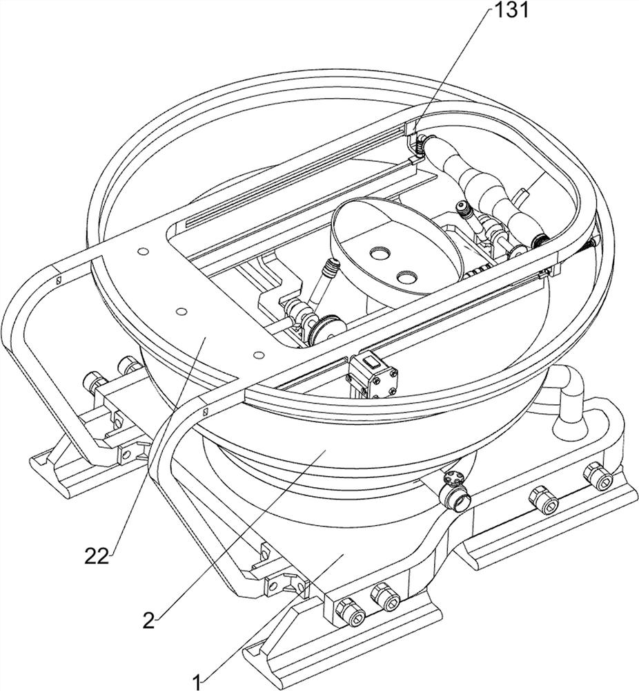
[0033] A kind of anorectal anal cleaning equipment, such as Figure 1-4 As shown, it includes a base 1, a housing 2, a fixed plate 21, a connecting frame 22, a seat plate 3, a mounting frame 4, a first shaft 5, a first connecting pipe 6, a spray head 7, a connecting head 8, and a connecting component 9 And the swing assembly 11, the top of the base 1 is connected to the housing 2, the top of the housing 2 is connected to the connecting frame 22, the bottom of the connecting frame 22 is connected to the left side of the base 1, and the upper inner walls of the front and rear sides of the housing 2 are connected to the fixing plate 21. The top of the connecting frame 22 is connected with the seat plate 3 by means of bolt connection, the seat plate 3 cooperates with the shell 2, the seat plate 3 has an opening, and two mounting frames 4 are connected between the bottoms of the two fixing plates 21 , the two installation frames 4 are left and right symmetrical, the middle part of ...
Embodiment 2
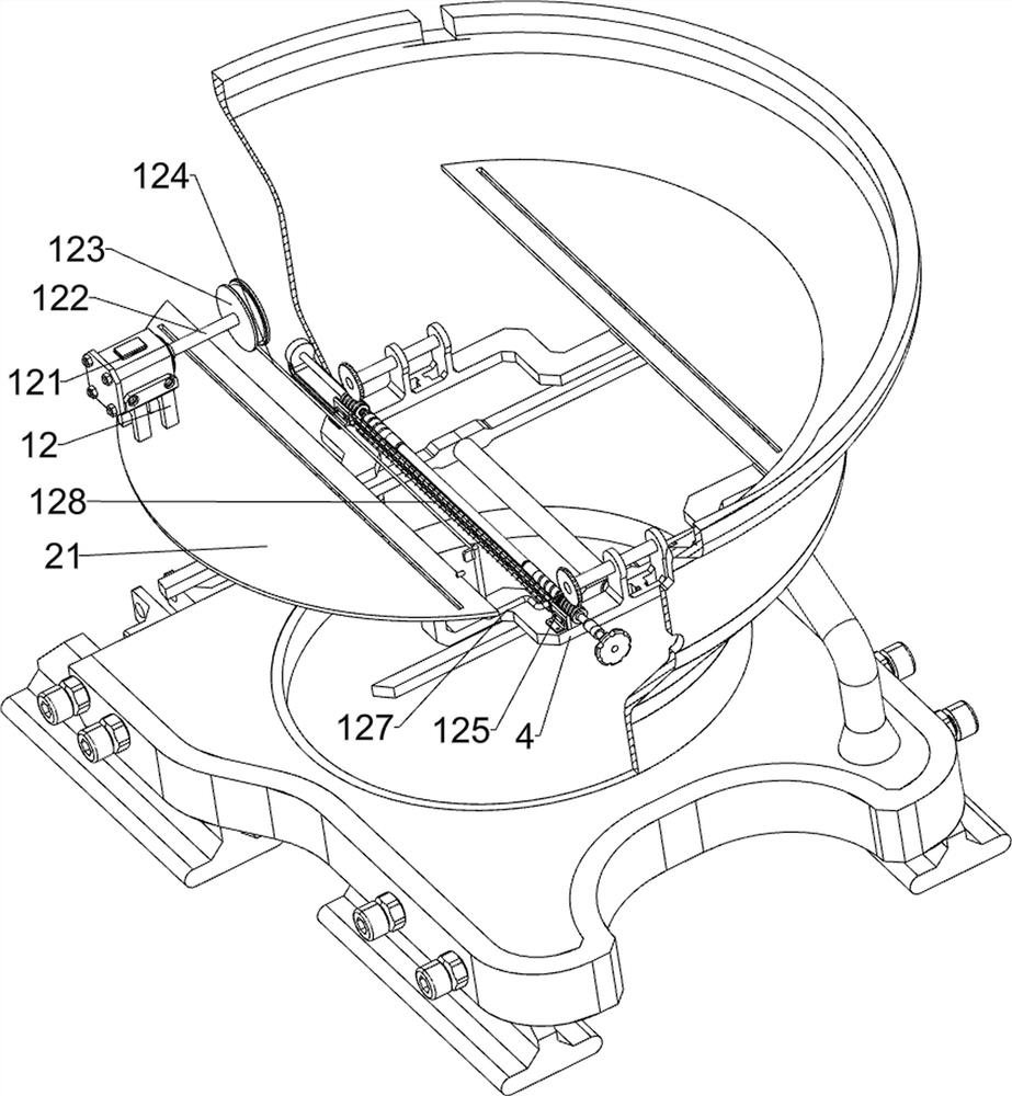
[0038] On the basis of Example 1, such as Figure 5-6 As shown, a drive assembly 12 is also included, and the drive assembly 12 includes a servo motor 121, a rotating shaft 122, a first winding wheel 123, a first pull wire 124, a guide rail 125, a movable frame 127, a return spring 128 and a third shaft 1291 , a servo motor 121 is installed on the left side of the top of the front side fixing plate 21, the output shaft of the servo motor 121 is connected to a rotating shaft 122 through a coupling, and a first reel 123 is connected to the rotating shaft 122, and the front of the two installation frames 4 A guide rail 125 is connected between the parts, a movable frame 127 is slidably connected on the guide rail 125, a first backguy 124 is wound on the first winding wheel 123, the tail end of the first backguy 124 is connected with the movable frame 127, and the movable frame 127 is connected with the movable frame 127. Two return springs 128 are connected between the guide rail...
Embodiment 3
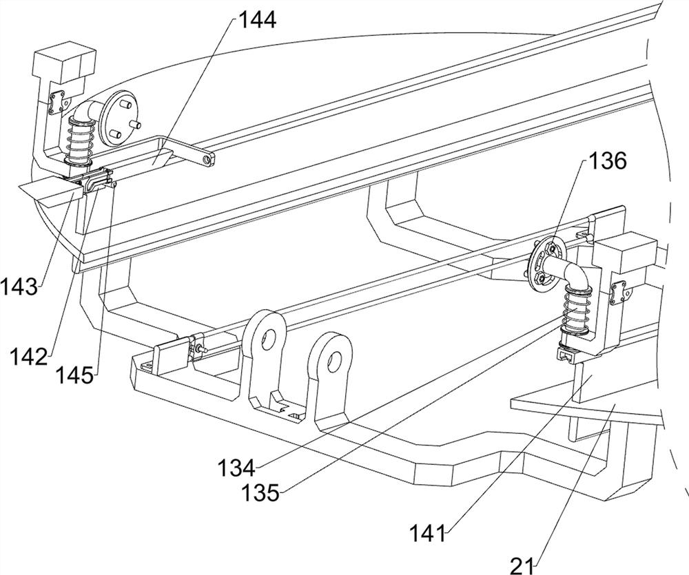
[0041] On the basis of Example 2, such as Figure 7-8 As shown, the wiping assembly 13 is also included, and the wiping assembly 13 includes a sliding frame 131, a first connection block 132, a tension spring 133, a slide bar 134, an elastic member 135, a rotating disk 136, a wiping roller 137 and a connecting plate 138, which are connected The upper part of the frame 22 is slidably connected with a sliding frame 131, the front and rear sides of the bottom of the sliding frame 131 are connected with a first connecting block 132, and a tension spring 133 is connected between the first connecting block 132 and the housing 2, and the first connecting block 132 is slidably connected with a slide bar 134, and an elastic member 135 is connected between the slide bar 134 and the first connecting block 132, and the top of the slide bar 134 is connected with a turntable 136 through bearing rotation, and a wiping roller is set between the two turntables 136 137, the left side of the fir...
PUM
 Abstract
Description
Claims
Application Information
 - R&D
- Intellectual Property
- Life Sciences
- Materials
- Tech Scout
- Unparalleled Data Quality
- Higher Quality Content
- 60% Fewer Hallucinations
Browse by: Latest US Patents, China's latest patents, Technical Efficacy Thesaurus, Application Domain, Technology Topic, Popular Technical Reports.
© 2025 PatSnap. All rights reserved.Legal|Privacy policy|Modern Slavery Act Transparency Statement|Sitemap|About US| Contact US: help@patsnap.com


