
Die cutting machine for food packaging carton production

A food packaging and die-cutting machine technology, applied in the directions of packaging, transportation and packaging, papermaking, etc., can solve the problems of reducing the efficiency of cardboard die-cutting, equipment jams, scrapping, etc. The effect of preparation efficiency

Inactive Publication Date: 2021-10-01
GUANGXI ECO ENG VOCATIONAL & TECHN COLLEGE
View PDF19 Cites 0 Cited by
  • Summary
  • Abstract
  • Description
  • Claims
  • Application Information

AI Technical Summary

Problems solved by technology

The cardboard is die-cut, indented, and stamped by a die-cutting machine to prepare the required cartons. Among them, the types of die-cutting machines are divided into circular die-cutting machines, circular die-cutting machines, and flat-pressing die-cutting machines. There are three types of machines, and the existing die-cutting machine for food packaging carton production, in the process of embossing and die-cutting the carton, the die-cutting embossing plate in the device is easy to leave shredded paper pieces produced by the die-cutting cardboard , damage the die-cutting embossing plate, resulting in incomplete die-cutting and embossing of the subsequent cardboard, causing sticking, resulting in misalignment of the cardboard, reducing the quality of the cardboard die-cutting, or even scrapping, and in the process of die-cutting large quantities of cardboard, The equipment will generate a lot of heat, which cannot be dissipated in time, and it will be transferred to the cardboard, resulting in an increase in the softness of the cardboard, making the equipment prone to paper jams, and reducing the efficiency of cardboard die-cutting

Method used


Image

  • Die cutting machine for food packaging carton production
  • Die cutting machine for food packaging carton production
  • Die cutting machine for food packaging carton production

Examples


Embodiment Construction

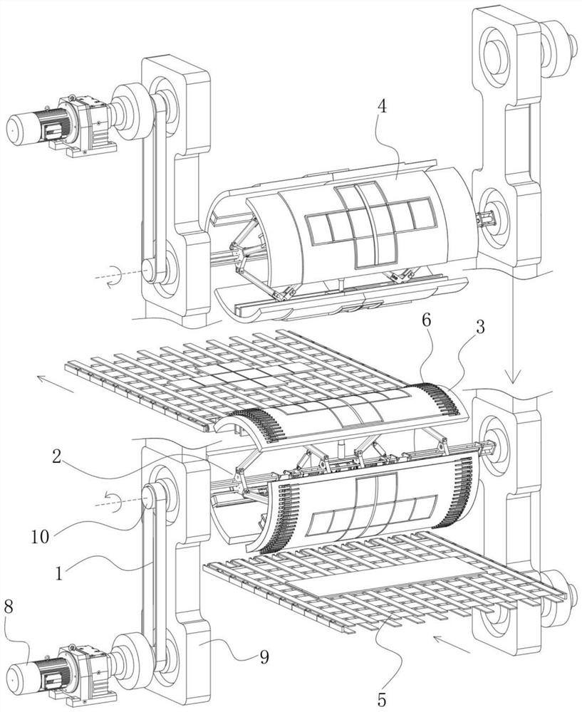
[0032] refer to Figure 1-4 , the present invention provides a technical solution: a die-cutting machine for food packaging carton production, which includes:

[0033] The driving device 1 is provided with two groups, and is symmetrically arranged up and down;

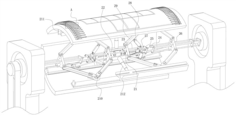
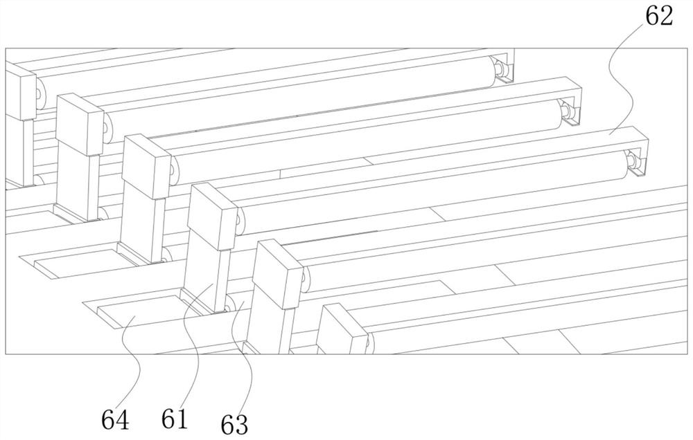
[0034] The rolling support 2 is in a cylindrical structure, and two groups are provided, which are respectively installed in the driving device 1 above and below. The die-cutting embossing plate 4 is installed on the outer side of the rolling support above, and the outer side of the rolling support below is installed. There are fixed templates 3, all of which are circular arc plate structures, with a central angle of 90°, and a clamping assembly 6 is installed near the left and right side arc edges of the fixed template 3, and an elastic pusher 7 is installed inside the fixed template, and Multiple groups are arranged along the arc surface, and the central angle is set at 90°, which can ensure that the arc surface is ...


PUM


Abstract

The invention discloses a die cutting machine for food packaging carton production. The die cutting machine comprises two groups of driving devices which are symmetrically arranged up and down; two groups of rolling supports, wherein the rolling supports are of a cylindrical structure and are installed in the driving devices on the upper portion and the lower portion correspondingly, die cutting impressing plates are installed on the outer side of the rolling support on the upper portion, fixed templates are installed on the outer side of the rolling support on the lower portion, the die cutting impressing plates and the fixed templates are both of an arc plate structure, pressing and clamping assemblies are installed at the positions close to the arc edges of the left sides and the right sides of the fixed templates, and a plurality of groups of elastic pushing parts are arranged in the fixed templates along the cambered surfaces of the fixed templates; and two groups of material conveying devices which are installed on the right sides of the lower portions and the left sides of the upper portions of the fixed templates correspondingly and used for inputting and outputting paper boards, wherein the material conveying device on the upper portion is lower than the tangent horizontal plane of the fixed template on the uppermost portion.

Description

technical field [0001] The invention relates to the technical field of food packaging carton production, in particular to a die-cutting machine for food packaging carton production. Background technique [0002] Packaging cartons play an important role in containing, protecting products and looking beautiful. The cardboard is die-cut, indented, and stamped by a die-cutting machine to prepare the required cartons. Among them, the types of die-cutting machines are divided into circular die-cutting machines, circular die-cutting machines, and flat-pressing die-cutting machines. There are three types of machines, and the existing die-cutting machine for food packaging carton production, in the process of embossing and die-cutting the carton, the die-cutting embossing plate in the device is easy to leave shredded paper pieces produced by the die-cutting cardboard , damage the die-cutting embossing plate, resulting in incomplete die-cutting and embossing of the subsequent cardboa...

Claims


Application Information

Patent Timeline
IPC IPC(8): B31B50/20B31B50/00B26D7/18
CPCB31B50/20B31B50/006B26D7/18
Inventor 李萍宁桂杏戴亮甘进包力源
Owner GUANGXI ECO ENG VOCATIONAL & TECHN COLLEGE
Learn More