Automatic shredding and binding machine

A tie machine and wire cutting technology, which is applied in filament/thread forming, textile and papermaking, fiber processing, etc., can solve problems such as relatively high requirements for manual proficiency, affecting the service life of the wire take-up wheel, and increasing production costs, etc. Achieve the effect of ensuring product quality, saving labor and improving efficiency

Pending Publication Date: 2021-10-01
江西爱科道环境科技发展有限公司 +1
View PDF0 Cites 0 Cited by
  • Summary
  • Abstract
  • Description
  • Claims
  • Application Information

AI Technical Summary

Problems solved by technology

However, there is a problem of wasting manpower in this method, because as far as the film cutting operation of a spinning machine is concerned, it needs the cooperation of two workers to complete, and then one person is needed to wash the film silk and bind it, and because the cut film The ends of the filaments are required to be relatively neat, so it is necessary to soak the membrane filaments in water first, then align them one by one, and finally tie them with ropes and tie them in knots, so that the filaments can be hung and dried in the future.
According to the normal spinning speed, it takes about 2-3 minutes to cut once, which requires relatively high manual proficiency, and if the silk is cut in this way for a long time, there will be knife marks on the take-up wheel of the spinning equipment, and there will be too many knife marks , the membrane yarn may be scratched, the membrane yarn produced in this way will be unqualified, and it will also affect the service life of the take-up wheel
This method not only wastes labor costs, increases production costs, but also may affect product quality

Method used


Image

  • Automatic shredding and binding machine
  • Automatic shredding and binding machine
  • Automatic shredding and binding machine

Examples


Embodiment Construction

[0035] The present invention will be further described in detail below through the specific examples, the following examples are only descriptive, not restrictive, and cannot limit the protection scope of the present invention with this.

[0036] In describing the present invention, the terms "upper", "lower", "left", "right", "inner", "outer", "front end", "rear end", "head" unless otherwise specified The orientation or positional relationship indicated by , "tail", etc. is based on the orientation or positional relationship shown in the drawings, and is only for the convenience of describing the present invention and simplifying the description, rather than indicating or implying that the referred device or element must have a specific orientation , constructed and operated in a particular orientation and therefore should not be construed as limiting the invention. In addition, the terms "first", "second", "third", etc. are used for descriptive purposes only and should not b...


PUM


Abstract

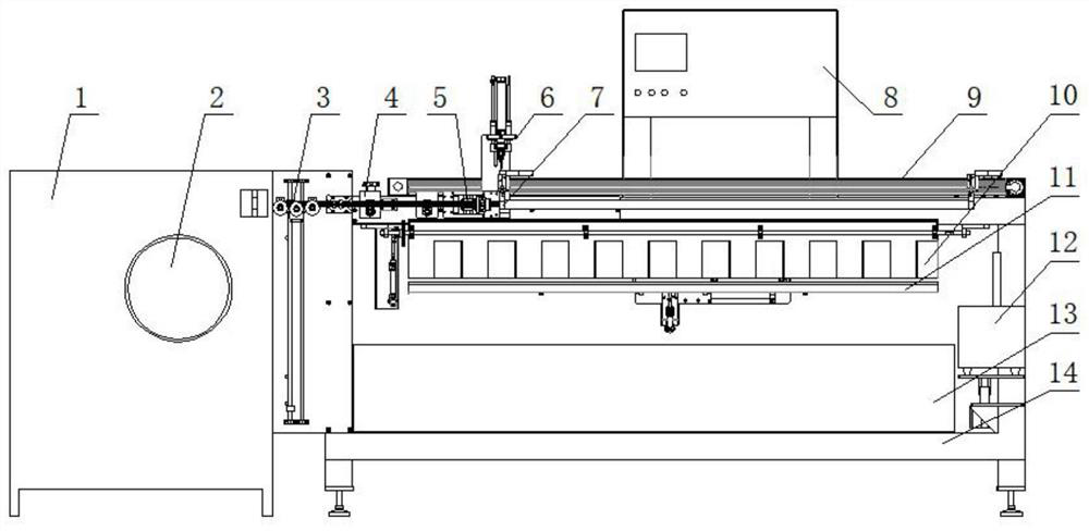
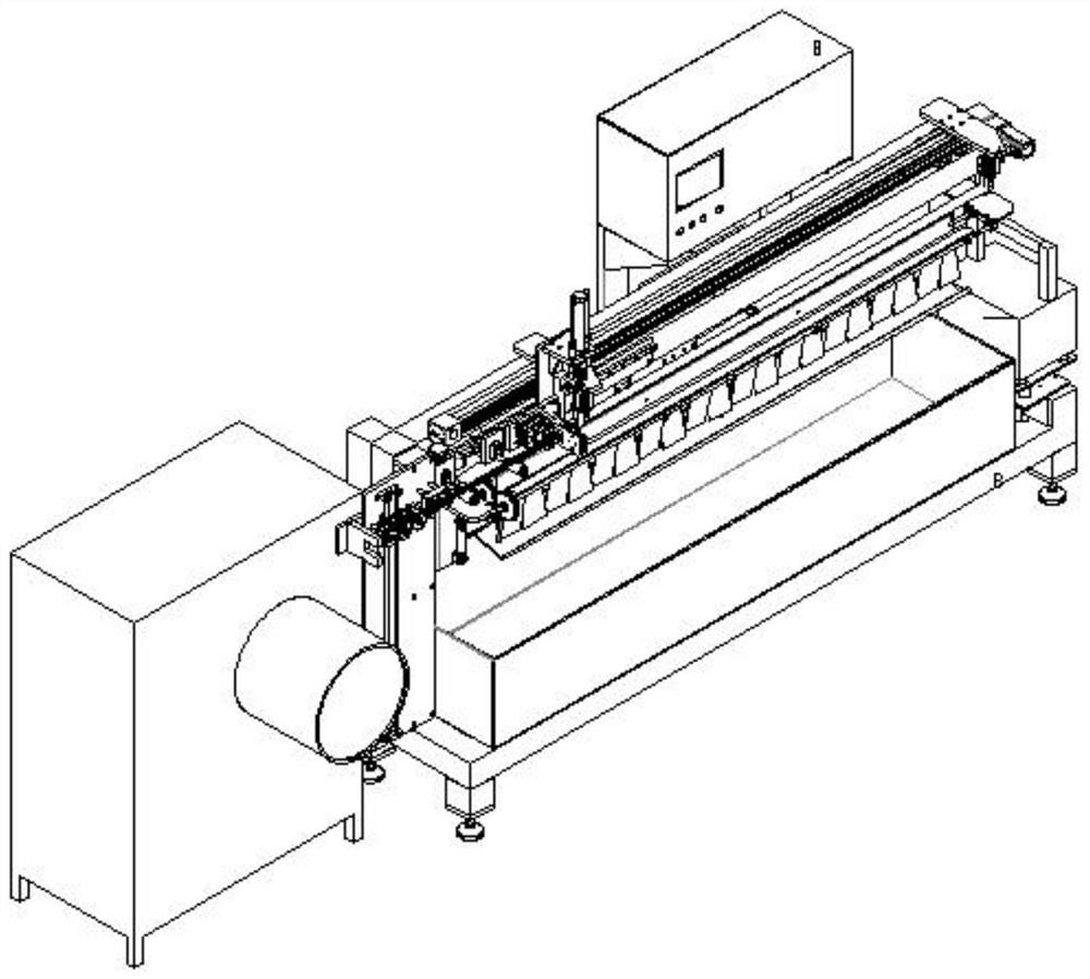
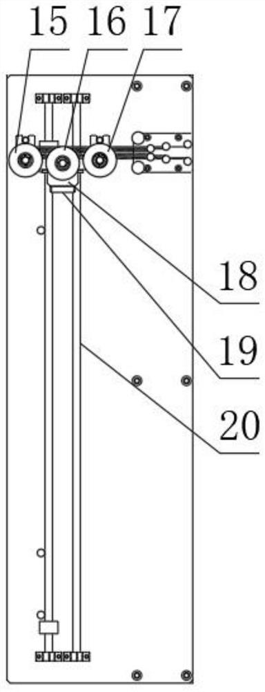
The invention relates to an automatic shredding and binding machine. The automatic shredding and binding machine is characterized by comprising a shredding unit, a wire supporting and releasing moving unit and a binding unit; the shredding unit comprises a tension wire releasing mechanism, a wire pressing moving mechanism, a shredding mechanism and a wire clamping moving mechanism; the wire pressing moving mechanism is arranged on the right side of the tension wire releasing mechanism; the shredding mechanism capable of moving up and down is arranged on the right side of the wire pressing moving mechanism; the wire clamping moving mechanism capable of moving left and right is arranged below the shredding mechanism; the wire supporting and releasing moving unit is arranged below the wire clamping moving mechanism; and the binding belt unit is installed on the right side of the wire supporting and releasing moving unit in a lifting mode. The automatic shredding and binding machine is scientific and reasonable in design, has the advantages of saving labor, improving the shredding and binding efficiency, ensuring the product quality, being easy to implement and the like, and has relatively high innovativeness.

Description

technical field [0001] The invention belongs to the field of spinning equipment, and relates to a cable tie machine, in particular to an automatic silk-cutting cable tie machine. Background technique [0002] The membrane filaments produced by the spinning equipment need to be manually cut, bundled and inspected manually to ensure the pass rate of the membrane filaments. However, this method has the problem of wasting manpower, because as far as the operation of cutting the film yarn of a spinning machine is concerned, it needs the cooperation of two workers to complete, and then one person is needed for washing the film silk and bundling, and because the cut film The ends of the filaments are required to be relatively neat, so it is necessary to soak the membrane filaments in water first, then align them one by one, and finally tie them with ropes and tie them in knots for subsequent hanging and drying. According to the normal spinning speed, it takes about 2-3 minutes to ...

Claims


Application Information

Patent Timeline
Patent Type & Authority Applications(China)
IPC IPC(8): D01D5/42D01D13/02
CPCD01D5/423D01D13/02
Inventor 王永超李丹郑先强谷国军刘沐之王晓龙武彪胡友平
Owner 江西爱科道环境科技发展有限公司
Why Eureka
Try Eureka