Quick exhaust valve with overpressure protection function

A technology of overpressure protection and exhaust valve, applied in the direction of functional valve type, valve details, multi-way valve, etc., can solve the problems of inconvenient pipeline connection, large occupied volume, and many pneumatic components, so as to enhance the reliability of long-term use , Easy to disassemble and replace, avoiding the effect of contact wear

Active Publication Date: 2021-10-01
ZHEJIANG CHEER TECH CO LTD
View PDF7 Cites 0 Cited by
  • Summary
  • Abstract
  • Description
  • Claims
  • Application Information

AI Technical Summary

Problems solved by technology

In pneumatic applications that require rapid exhaust, such as bellows pumps, it is generally necessary to install a relief valve and a quick exhaust valve at the same time. There are many pneumatic components, which occupy a large volume, inconvenient pipeline connection, and high cost.

Method used


Image

  • Quick exhaust valve with overpressure protection function
  • Quick exhaust valve with overpressure protection function
  • Quick exhaust valve with overpressure protection function

Examples


Embodiment 1

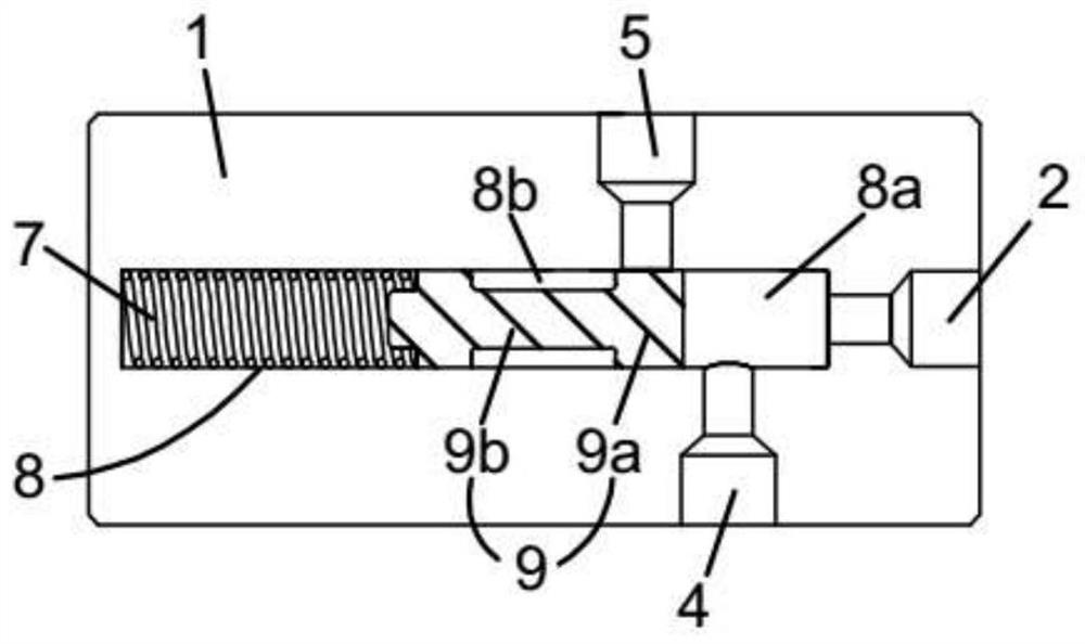
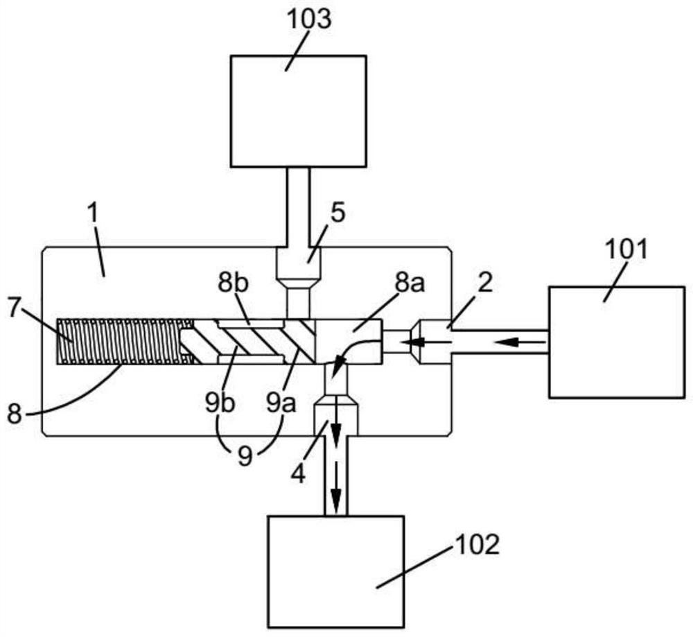
[0035] Such as figure 2 As shown, this embodiment provides a quick exhaust valve with an overpressure protection function, including a valve body 1, the valve body 1 has three valve ports and a valve cavity 8, and the three valve ports are respectively the first valve port 2. The second valve port 4 and the third valve port 5; the first valve port 2 communicates with the air source 101 outside the quick exhaust valve, and the second valve port 4 communicates with the actuator 102 outside the quick exhaust valve. The third valve port 5 is connected with the discharge environment 103 outside the quick exhaust valve.

[0036]A reversing mechanism is provided in the valve cavity 8, the reversing mechanism includes a spring 7 and a valve core 9, the spring 7 is located between one end of the valve core 9 and the wall of the valve cavity 8, the valve core 9 can reciprocate in the valve cavity 8; The spool 9 divides the valve cavity 8 into at least two mutually isolated first chamb...

Embodiment 2

[0045] Figure 6 Another embodiment of the quick exhaust valve shown in the present invention is shown. The difference between this embodiment and Embodiment 1 is that the valve body 1 has four valve ports, and the fourth valve port 6 is arranged on the third Near the valve port 5, more preferably, the fourth valve port 6 and the third valve port 5 are coaxially arranged, and the flow path between the two is basically linear; the second valve port 4 and the fourth valve port 6 are connected to the The actuator 102 outside the quick exhaust valve is connected, the gas enters the actuator 102 through the second valve port 4 , and the gas to be discharged in the actuator 102 is discharged outside through the fourth valve port 6 .

[0046] Figure 7-9 The working principle of the quick exhaust valve described in this embodiment under different gas pressure states is shown:

[0047] Such as Figure 7 As shown, when the intake pressure is higher than the opening pressure and lowe...

Embodiment 3

[0053] Figure 10 Another embodiment of the quick exhaust valve shown in the present invention is shown. The difference between this embodiment and Embodiment 1 or 2 is that a valve sleeve 12 is fixedly installed in the valve cavity 8 of the valve body 1, and the valve sleeve 12 It is made of high wear-resistant and self-lubricating materials such as ceramics or PTFE; the outer side of the valve sleeve 12 and the inner side of the valve cavity 8 can be respectively provided with external threads and internal threads, and the valve sleeve 12 is installed in the valve cavity 8 through threaded connections .

[0054] The valve sleeve 12 is provided with openings corresponding to the first valve port 2, the second valve port 4, the third valve port 5 and the fourth valve port 6 respectively, and a reversing mechanism is provided in the valve sleeve 12, and the reversing mechanism includes Spring 7 and spool 9, one side of spring 7 is connected with the inner side wall of valve sl...


PUM


Abstract

The invention discloses a quick exhaust valve with an overpressure protection function, which comprises a valve body, a valve cavity and a reversing mechanism arranged in the valve cavity, wherein the valve body is provided with a first valve port, a second valve port and a third valve port; the reversing mechanism divides the valve cavity into at least a first cavity and a second cavity which are separated from each other; the first valve port, the first cavity and the second valve port can be communicated to form an air inlet channel, the second valve port, the second cavity and the third valve port can be communicated to form an exhaust channel, and the first valve port, the first cavity and the third valve port can be communicated to form an overpressure protection channel; the reversing mechanism can directionally move or deform under air supply pressure and selectively communicate with the air inlet channel, the exhaust channel or the overpressure protection channel. The quick exhaust valve has the quick exhaust and pressure limiting functions, can save pressure limiting devices such as an overflow valve in a pneumatic system, and reduces complexity and cost of the system.

Description

technical field [0001] The invention relates to the technical field of pneumatic components, in particular to a quick exhaust valve with an overpressure protection function. Background technique [0002] Quick exhaust valve is a pneumatic component used to quickly discharge gas under pressure. Existing quick exhaust valves such as figure 1 As shown, there are three valve ports, which are the inlet valve port S2 connected with the air source, the outlet valve port S4 connected with the actuator, and the exhaust valve port S5 connected with the discharge environment. The quick exhaust valve There is a reversing mechanism inside to change the flow direction of the connecting valve port. Under the intake condition, the inlet valve port S2 and the outlet valve port S4 are connected, and under the exhaust condition, the outlet valve port S4 and the exhaust valve are connected. Port S5. [0003] The reversing mechanism inside the quick exhaust valve generally has an automatic re...

Claims


Application Information

Patent Timeline
IPC IPC(8): F16K17/04F16K11/044F16K27/02
CPCF16K17/0473F16K27/0263
Inventor 薛飞俞健行袁仕芳何元杰徐宁付婧媛
Owner ZHEJIANG CHEER TECH CO LTD
Why Eureka
Try Eureka