Temperature monitoring system and temperature monitoring method thereof
A monitoring system and temperature value technology, applied in radiation pyrometry, measuring devices, instruments, etc., can solve problems such as abnormal temperature of heating parts that increase costs, and achieve the effects of improved safety, timely response, and low cost
Pending Publication Date: 2021-10-01
CHIPSEA TECH SHENZHEN CO LTD
7 Cites 3 Cited by
AI-Extracted Technical Summary
Problems solved by technology
[0006] The technical problem to be solved by the present invention is to provide a temperature monitoring system and its temperature monitoring method to solve th...
Method used
Embodiments of the present invention set temperature detection range to cover the temperature detection device 3 of a plurality of electric meters 2 in meter box 1, and this temperature detection device 3 is by at least one thermopile sensor 31 and the monitoring that is electrically connected with thermopile sensor 31 Module 32 constitutes, wherein, the sensing surface of thermopile sensor 31 faces each ammeter 2 to detect the temperature of the preset position in each ammeter 2 in real time, and this preset position can be set as the component position that is easy to generate heat when the ammeter 2 is abnormal, such as the ammeter 2 terminals, wires or other locations. Since the detection range of a single thermopile sensor 31 can cover multiple electric meters 2 in the electric meter box 1, and can be accurate to the preset positions in the electric meters 2, the temperature at the preset positions of the multiple electric meters 2 can be directly detected at the same time , without the need to scan the ammeters 2 one by one, so the temperature detection of the specific positions of the multiple ammeters 2 can be completed more quickly, and the thermopile sensor 31 can directly detect the heat generated by the terminals of the multiple ammeters 2 in the ammeter box 1 The temperature of the components, before the air temperature rises significantly, can judge whether there is an abnormal situation according to the temperature of the terminal and determine whether to perform a safety action. The response is more timely and sensitive, and the safety of the meter box 1 can be effectively improved. In addition, at least one thermopile sensor 31 is needed to detect the preset positions of multiple ammeters 2 , which is cheaper than installing a thermistor sensor at each preset position of the ammeters 2 .
In the embodiment of the present invention, because single thermopile sensor can directly detect the temperature of the preset position of a plurality of ammeters at the same time, without needing to scan successively of ammeters one by one, it is therefore possible to complete the detection of a plurality of ammeters more quickly. Temperature detection at a specific location. Moreover, the thermopile sensor can directly detect the temperature of heating components such as the terminals of multiple meters in the meter box. Before the air temperature rises significantly, it can judge whether there is an abnormality according to the temperature of the terminals. Whether to perform safety actions, the response is more timely and sensitive, which can effectively improve the safety of the meter box. In addition, at least one thermopile sensor is needed to detect preset positions in multiple electric meters, which is cheaper than installing a thermistor sensor at the preset position of each electric meter.
It can be understood that the present embodiment judges whether the temperature in the monitoring area is based on the difference between the first t...
Abstract
The invention provides a temperature monitoring system and a temperature monitoring method thereof. The temperature monitoring system comprises an electricity meter box, one or more electricity meters arranged in the electricity meter box and a temperature detection device arranged in the electricity meter box, and the temperature detection range of the temperature detection device covers each electricity meter; the temperature detection device comprises a thermopile sensor and a monitoring module electrically connected with the thermopile sensor, the sensing surface of the thermopile sensor faces each electricity meter, and the thermopile sensor is used for detecting the temperature of a preset position in each electricity meter; and the monitoring module is used for judging whether the temperature of the preset position in each electricity meter is abnormal or not, and executing a preset safety action when the temperature of the preset position in each electricity meter is abnormal. The temperature monitoring system and a temperature monitoring method thereof can effectively improve the fault predictability and safety of the electricity meter box, and reduce the damage rate of each electricity meter in the electricity meter box.
Application Domain
Pyrometry using electric radation detectors
Technology Topic
Automotive engineeringElectricity meter +3
Image
Examples
- Experimental program(1)
Example Embodiment
[0049]In order to make the objects, technical solutions and advantages of the present invention, the present invention will be described in detail below with reference to the accompanying drawings and examples, in which the same or similar components are identical or similar or similar. element. It should be understood that the specific embodiments described herein are merely intended to illustrate the invention and are not intended to limit the invention. Moreover, the technical features of the various embodiments of the invention described below may be combined as long as they do not constitute a collision between each other.
[0050] To this end, embodiments of the present invention provide a temperature monitoring system, and a temperature monitoring method of the temperature monitoring system.
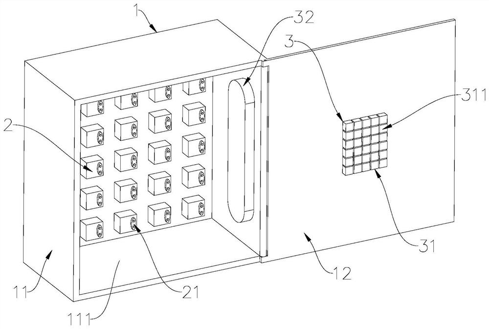
[0051] See figure 1 , figure 1 A structural diagram of a temperature monitoring system provided by an embodiment of the present invention.
[0052] like figure 1 As shown, the embodiment of the present invention provides a temperature monitoring system, including a meter box 1, one or more electric meter 2 disposed within the meter box 1 and disposed within the meter box 1 and the temperature detection range covers the temperature detection of each electric meter 2. Apparatus 3, wherein the temperature detecting device 3 includes a thermoelectric stack sensor 31 for detecting a temperature of each of the preset positions in each of each of the electrometer 2, and is electrically connected to the thermoelectric stack sensor 31 and is used to determine each meter 2. Whether the temperature in the preset position is abnormal, and the temperature of the preset safety action is performed when the temperature abnormality in each of the respective meter 2 is performed.
[0053] In practical applications, the thermoelectric stack sensor 31 detects the temperature of the predetermined position in each of each of the electric stack sensors 31, and the monitoring module 32 electrically connected to the thermoelectric stack sensor 31 determines whether or not each of the electric weights 2 has an abnormality in accordance with the temperature of the preset position in each of the meter 2. And execute the preset security action when each electric meter 2 occurs. Here, it is necessary to explain that the monitoring module 32 determines a certain critical state of the electricity meter 2 as a judgment condition according to the temperature of the preset position in each of each of the electrometics 2, that is, each of the either of the electric meter 1 can be judged as the judgment condition. Whether the electric meter 2 is abnormal.
[0054] The temperature monitoring system provided in the present invention provides a temperature detecting device 3 that covers all of the electric meter 2 in the electric meter box 1, and the temperature detecting device 3 is monitored by the thermoelectric stack sensor 31 and the thermoelectric stack sensor 31. Module 32 is configured, wherein the sensing surface of the thermoelectric stack sensor 31 is in real time to detect the temperature of the predetermined position in each of the electric weights in real time. Based on this, during the operation of each electric meter 2 in the electric meter 1, the thermoelectric stack sensor 31 detects the temperature of the predetermined position in each of the electric weights 2 in real time, and the monitoring module 32 electrically connected to the thermoelectric stack sensor 31 is preset in each of the electricity meter 2. The temperature of the position determines whether each of the electric meter 2 has an abnormality and performs a preset security action when the electrical meter 2 occurs.
[0055] The embodiment of the present invention detects and acquires the temperature of the predetermined position in each of the electric stack sensors 31, and the temperature condition that is usually conformal to when a certain or more faults occur in one or more faults, judges by monitoring module 32 Whether the temperature in each of the preset positions in each electric meter 2 meets this judgment condition, and the temperature of the preset position in each of the electric weights is in line with the preset safety action, thereby avoiding the abnormal conditions of the meter in the electric meter. .
[0056] The present invention provides a temperature detecting device 3 covering a plurality of electric meter 2 in the electric meter box 1, and the temperature detecting device 3 is constituted by a temperature detecting device 3 consisting of a monitoring module 32 electrically coupled to the thermopile sensor 31. Wherein, the sensing surface of the thermoelectric stack sensor 31 faces each of the preset positions in real time, which may be provided as a component position that is easily heated when an electric meter 2 occurs, such as an electric meter 2. Terminal, wires or other locations. Since the detection range of a single thermoelectric stack sensor 31 can cover the plurality of electricity meas 2 in the meter box 1, and can accurately to the preset position in the electric meter 2, the temperature of the preset position of the plurality of electricity meas 2 can be directly detected. No need to scan one by one electrometer 2, so that the temperature detection of a specific position of the plurality of electric meter 2 can be completed more quickly, and the thermopile sensor 31 can directly detect the terminals such as the plurality of electricity meter 2 in the meter box 1. The temperature of the component, before the air temperature is obviously increased, it is possible to determine whether there is abnormal conditions according to the temperature of the terminal block and determine whether the security action is performed, and the response is more timely, sensitive, and can effectively improve the safety of the electric meter 1. In addition, at least one thermoelectric stack sensor 31 can detect the preset position in the plurality of electricity meter 2, which is more cost-effective to install the thermistor sensor compared to the preset position of each of the meter 2.
[0057] Please refer to figure 2 , figure 2 A front elevational view of the temperature monitoring system provided by the embodiment of the present invention.
[0058] As a feasible embodiment, such as figure 2 As shown, the thermoelectric stack sensor 31 can include a plurality of sub-thermal stacks 311, and the plurality of sub-thermal stacks 311 may be array distribution, and the inductive surfaces of each sub-thermopile 311 may be toward a plurality of electric meter 2.
[0059] The array distribution shape of the plurality of sub-thermal stacks 311 can be rectangular. Of course, it is not limited thereto, in other embodiments, the array distribution shape of the plurality of sub-thermal stacks 311 can also be a triangular, circular, trapezoidal, polygon, and any one or at least two combinations of other common patterns in the art. . It should be understood that the array distribution shape of the plurality of sub-thermal stacks 311 is determined according to the actual application scenario, and the embodiment of the present invention is not limited.
[0060] Further, the meter box 1 can be divided into a plurality of monitoring regions 4, each monitoring area 4 can be provided with at least one meter 2, at this time, each sub-thermal stack 311 can be used to detect a monitoring area 4, respectively. The temperature of the preset position in the electric meter 2. Preferably, just as figure 2 The example given, each monitoring area 4 is provided with an electric meter 2.
[0061] Typically, each of the electric meter has a terminal terminal for connecting a wire. Based on this, in the embodiment of the present invention, each of the electric meter 2 may have one or more terminals 21 for connecting the wire, at this time, the preset position mentioned above can be the position of the terminal 21. Alternatively, the position of the wire connected to the wiring terminal 21, or in the electric meter 2, in any position outside the wire terminal 21, or in the above position, at least two positions in the above position.
[0062] Further, the meter box 1 may include a casing 11 having an opening 111 and a box door 12 disposed to be connected to the casing 11. At this time, each of the electric weights can be disposed inside the casing 11 and the terminal block 21. The opening 111, the thermopile sensor 31 can be disposed in the inner surface of the box door 12 and toward the opening 111 when the box door 12 is closed. It is not difficult to see from this, the embodiment of the present invention sets each of the electrometics 11 inside the casing 11, and causes the terminal 21 of each of the electric weights 2 to open toward the opening 111, and the heat generator 31 is disposed on the inner surface of the box door 12. The inductive surface of the thermoelectric stack sensor 31 can be toward each of the electrometics 2 when the box door 12 is turned off, specifically the preset position (such as a terminal 21), which will facilitate the thermoelectric stack sensor 31 for each electrometer 31. The full coverage of the preset position in the electric meter 2, that is, it is conducive to the full detection of the temperature of the thermoelectric stack sensor 31 for the temperature of the preset position in each of the electric weights, and does not cause omissions to detect the temperature of the preset position in some of the electricity measters 2.
[0063] Further, the monitoring module 32 can include a protective unit for performing power-off protection, one end of the protection unit can be electrically connected to the thermopile sensor 31, and the other end of the protection unit can be electrically connected to each of the electric weights 2. Here, the purpose of setting the protection unit is, when the monitoring module 32 determines that each of the electric weights 2 is abnormal according to the temperature of the preset position in each of the electric weights, each of the electric weights 2 is turned off. As an embodiment, the protection unit can be connected to the circuit breaker of each of the electric weights 2, or built into the circuit breaker in each of the electric weights 2, by the control of the circuit breaker, the power-off protection of each of the electric weights 2 is realized.
[0064] For the configuration of the monitoring module 32, it is not limited to the protection unit mentioned above, in other embodiments, the monitoring module 32 may include other common structures, such as alarm, etc., such as alarm, etc. Of course, the configuration of the monitoring module 32 can also be a combination of a variety of structures, such as a combination of protection units and alarms, and the like. It should be understood that what is the specific configuration of the monitoring module 32 to be determined according to the actual application scenario, the embodiments are not limited.
[0065] See image 3 , image 3 A flow schematic of a temperature monitoring method provided by the embodiment of the present invention.
[0066] like image 3 As shown, the embodiment of the present invention further provides a temperature monitoring method, applied to the above temperature monitoring system provided by the embodiment of the present invention, which includes steps 11 to 13.
[0067] Step 11, divide the meter box 1 into a plurality of monitoring regions 4, each monitoring area 4 including at least one target position;
[0068] In the embodiment of the present invention, it is necessary to divide the meter box 1 into a plurality of monitoring regions 4, and set at least one target position in each monitoring area 4 to set the temperature value of the target position as subsequent judgment meter 1. Whether the electric meter 2 has an abnormal basis.
[0069] Specifically, the target position is the preset position mentioned above, i.e., the target position includes the position of the terminal 21 of the electric meter 2, or the position of the wire connected to the terminal 21, or, the electrometics 2 removing wiring The terminal 21 and an arbitrary position outside the wire connected to the terminal 21, or a combination of at least two positions in the above position.
[0070] Step 12, monitor the temperature value of each target position, respectively;
[0071] In the embodiment of the present invention, the temperature value of each target position can be acquired by the thermopile sensor 31, wherein each of the thermostile sensor 31 may correspond to a monitoring area 4.
[0072] Step 13, when the temperature value of at least one target position meets the preset temperature abnormal condition, the preset security action is performed.
[0073] In the embodiment of the present invention, after the temperature value of each target position is acquired by the thermopile sensor 31, it is possible to determine whether the meter 2 in each of the target positions has an abnormality in each of the target positions, specifically: if at least one temperature The value is in line with the preset temperature abnormal condition (characterizing an abnormality of the corresponding electric meter 2), performs preset safety actions, such as power off protection, alert, or power-on protection, and the combination of both the alarm. It should be understood that the preset safety action is not limited thereto, in other embodiments, the preset security operation can also be a combination of other actions or various actions commonly used in the art, the embodiment of the present invention. Do not limit this.
[0074] In an embodiment of the present invention, since the single thermoelectric stack sensor can simultaneously detect the temperature of the preset position of the plurality of meters, no need to scan one by one meter, so it can complete the specific position of multiple meters more quickly. Temperature detection, and, the thermoelectric stack sensor can directly detect the temperature of the heat generating member such as the terminals of the plurality of meters in the meter box, and before the air temperature is significantly increased, it is possible to determine whether there is abnormal conditions according to the temperature of the terminal block and determine whether to perform security. Action, response is more timely, sensitive, and can effectively improve the safety of the meter box. In addition, at least one thermoelectric stack sensor can detect the preset positions in multiple meters, compared to the installation of the thermistor sensor in the preset position of each meter, the cost is more low.
[0075] In the embodiment of the present invention, the temperature monitoring method described above may have a variety of embodiments, which combined below.Figure 4 to 8 Some embodiments of the above temperature monitoring methods are described in detail.
[0076] like Figure 4 As shown, one embodiment of the temperature monitoring method according to the embodiment of the present invention includes steps 21 through 24 below.
[0077] Step 21, divide the meter box 1 into a plurality of monitoring zones 4, and each monitoring area 4 includes at least one target position;
[0078] Step 22, each monitor the temperature value of each target position in the preset time, to obtain the maximum temperature value and minimum temperature value of each target position in the preset time;
[0079] Step 23: Calculate the temperature difference value of the maximum temperature value and the minimum temperature value of each target position in the preset time;
[0080] Step 24, when the temperature difference value of at least one target position reaches a preset first temperature threshold, performs a preset security action.
[0081] In the present embodiment, step 22 is a specific embodiment of the temperature value of each of the target positions, and steps 23 and steps 24 are performed when at least one of the temperature values meet the preset temperature abnormal conditions. A specific embodiment of the security action is set.
[0082] It is easy to see from steps 21 to 24, the present embodiment, by monitoring the maximum temperature value and the minimum temperature value within the preset time, and calculates the temperature of the maximum temperature value and the minimum temperature value of the target position in the preset time. Difference, once this temperature difference reaches a preset first temperature threshold, the temperature change in the preset time is large, which does not match the normal working state of the meter 2, therefore, when the target position is The maximum temperature value in the preset time is executed when the temperature difference of the minimum temperature value reaches the preset first temperature threshold, performs the preset security action. When the temperature change of the target position in the preset time is obvious, for example due to the short circuit, overcurrent, or other factors rises, according to the present embodiment, the temperature abnormality in the meter box can be quickly identified and the safety action is performed.
[0083] It will be appreciated that the present embodiment is implemented based on the maximum temperature difference within the preset time, ie, according to the temperature change in the target position, determines whether the corresponding electric meter has an abnormality, compared to only the target position is in certain The temperature monitoring method of time is judged, it is not easily affected by the ambient temperature, and it is possible to more accurately obtain an abnormal conclusion of the electric meter 2 corresponding to the target position.
[0084] like Figure 5 Here, another embodiment of the temperature monitoring method provided in the embodiment of the present invention includes steps 31 to 33 below.
[0085] Step 31, divide the meter box 1 into a plurality of monitoring zones 4, and each monitoring area 4 includes at least one target position;
[0086] Step 32, monitor the temperature value of each target position, respectively;
[0087] Step 33: Perform a preset security action when the temperature value of at least one target position reaches or exceeds a preset maximum temperature threshold.
[0088] In the present embodiment, the specific embodiment of step 13 is: the preset security operation is performed when the temperature value of the at least one target position reaches or exceeds the preset maximum temperature threshold. Among them, the preset maximum temperature threshold can be set according to the normal temperature range of each target position according to the normal operation of the power meter. For example, the power form is slightly heated during normal operation, and when the electrical energy table is normal, the normal temperature range of each target position is typically 25 ° C to 35 ° C, the above predetermined maximum temperature threshold can be greater than or equal to 35. ° C. When the temperature value of at least one target position exceeds the preset maximum temperature threshold, it indicates that there is overflow, short circuit, and power excessive power, etc., which may result in severe abnormal conditions of the target position, and need to perform power off and other protection measures.
[0089] From steps 31 to 33, the present embodiment is compared by monitoring the temperature value of the target position, and the temperature value of the target position is compared to the preset maximum temperature threshold, once the temperature value of the target position or exceeds the preset The highest temperature threshold, the temperature of the target position is too high, which does not match the normal operating state of the electric meter 2, so when the temperature value of the target position meets or exceeds the preset maximum temperature threshold, executing the preset security action .
[0090] It will be appreciated that the present embodiment determines whether the corresponding electric meter has an abnormality based on the temperature value of a certain time at a certain time. Figure 4 The embodiment shown is not required to wait for the preset time to detect the temperature change of the target position within the preset time, so it is possible to improve the detection efficiency and easier.
[0091] like Image 6 Yet another embodiment of the temperature monitoring method provided by the embodiment of the present invention includes steps 41 to 43 below.
[0092] Step 41, divide the meter box 1 into a plurality of monitoring zones 4, and each monitoring area 4 includes at least one target position;
[0093] Step 42, monitor the temperature value of each target position, respectively;
[0094] Step 43: Perform a preset security action when the temperature value of at least one target position reaches or below the preset minimum temperature threshold.
[0095] In the present embodiment, step 43 is a specific embodiment of step 13. Among them, the preset minimum temperature threshold can be set according to the normal temperature range of each target position according to the normal operation of the power meter. For example, the electric energy table is slightly heated during normal operation. If the normal temperature range of each target position is typically 25 ° C to 35 ° C, the predetermined low temperature threshold can be less than or equal to 25. ° C. When the temperature value of at least one target position is less than the preset minimum temperature threshold, it indicates that there may be a disconnection in the power supply network, or the electric energy meter may have a fault alarm such as a fault alarm, to troubleshoot the fault in time.
[0096] As it is easy to see from steps 41 to 43, the present embodiment compares the temperature value of the target position with the preset temperature threshold by monitoring the temperature value of the target position, and the temperature value of the target position is or less than the preset The lowest temperature threshold, the temperature of the target position is too low, which is not in accordance with the normal operating state of the meter 2, so the preset can be performed when the temperature value of the target position is or less than the preset minimum temperature threshold. Safety action.
[0097] It will be appreciated that the present embodiment determines whether the corresponding electric meter has an abnormality based on the temperature value of a certain time at a certain time. Figure 4 The embodiment shown is not required to wait for the preset time to detect the temperature change of the target position within the preset time, so it is possible to improve the detection efficiency and easier.
[0098] like Figure 7 As shown, still another embodiment of the temperature monitoring method provided in the embodiment of the present invention includes steps 51 to 54 below.
[0099] Step 51, divide the meter box 1 into a plurality of monitoring regions 4, and each monitoring area 4 includes at least one target position;
[0100] Step 52, monitor the temperature value of each target position, respectively;
[0101] Step 53, calculate the difference between the temperature value of each of the two target positions;
[0102] Step 54: When the difference in the temperature value of any two target positions reaches a preset second temperature threshold, the preset security action is performed.
[0103] In the present embodiment, steps 53 and 54 perform a specific embodiment of the preset security operation when at least one of the temperature values meets the preset temperature abnormal conditions.
[0104] It is easy to see from steps 51 to 54, and the present embodiment is monitored by monitoring the temperature value of each target position, and calculates the difference in temperature value of any two target positions, once this difference reaches a preset second temperature threshold, Characterization of these two target locations is large, this is the normal working state of the electric meter 2. Typically, each of the electric weights in the same meter box 1 is in normal operation, whether it is the temperature of the different target position in the electric meter 2, or the temperature of the corresponding target position in any two meter 2, is also normal. In the case, the difference in temperature value of each of the two target locations should not exceed the preset second temperature threshold. When the difference between the temperature value of any two target positions exceeds the preset second temperature threshold, the temperature abnormality in the electric meter box will be described, and a specific security action is required.
[0105] It will be appreciated that the present embodiment determines whether there is abnormality in the die box based on the difference in temperature values of any two target positions, here, any two target locations include two objects within the same monitoring area 4. The position, further includes the target position in any two monitoring zones 4, that is, the present embodiment is no longer limited to the same monitoring area 4, but is associated with another monitoring area 4, making it in judging and When the meter 2 corresponding to the target position is abnormal, it is more accurate.
[0106] like Figure 8 As shown, further embodiment of the temperature monitoring method provided in the embodiment of the present invention includes steps 61 to 64 below.
[0107] Step 61, divide the meter box 1 into a plurality of monitoring regions 4, and each monitoring area 4 includes at least one target position, the target position here includes a terminal 21 and a wire connected to the terminal 21;
[0108] Step 62, each monitor the first temperature value of each of the terminals 21, and a second temperature value of the wire connected to each of the terminals 21;
[0109] Step 63: Calculate the difference between the first temperature value of the monitoring area 4 and the second temperature value of the wire connected to the terminal 21;
[0110] Step 64, when any one of the first temperature values of the terminal 21 and the second temperature value of the wire connected to the wiring terminal 21 reaches a preset third temperature threshold, perform a preset security action. .
[0111] In the present embodiment, step 62 is a specific embodiment of step 12, and steps 63 and 64 perform a specific embodiment of performing a preset security action when at least one of the temperature values meets the preset temperature abnormal conditions. .
[0112] From steps 61 to 64, it is easy to see that the sixth temperature monitoring method provided by the embodiment of the present invention is suitable for application scenarios for the temperature of the terminal 21 and the temperature of the wire connected to the wiring terminal 21. The sixth temperature monitoring method is monitored by monitoring any of the first temperature values of the terminal 21 of the monitoring region 4 and the second temperature value of the wire connected to the terminal 21, and calculates the first monitoring area 4 inner terminal 21 A temperature value and the difference in the second temperature value of the wire connected to the terminal 21, once this difference reaches the preset third temperature threshold, the temperature of the terminal 21 and the temperature of the wire connected to the terminal 21 are connected. The difference is large, this is the normal working state of the electric meter 2. Generally, since the wire 21 and the wire connected to the terminal 21 are interconnected relationships, the temperature of the terminal 21 and the temperature of the wire connected to the terminal 21 should be the same or similar, and therefore, when any of the monitors 4 When the first temperature value of the inner terminal 21 and the difference between the second temperature value of the wire connected to the wiring terminal 21 reaches the preset third temperature threshold, the temperature abnormality in the electric meter box will indicate that the preset can be performed. Safety action.
[0113]It will be appreciated that the present embodiment determines whether the temperature in the monitoring area is abnormal based on the first temperature value of the terminal 21 and the second temperature value of the wire connected to the wiring terminal 21. That is, the present embodiment is no longer limited to one target position in the same monitoring area 4, but is associated with two target positions in the same monitoring area 4, and due to the temperature of the terminal 21 and the terminal 21 connected to the terminal 21. The temperature of the wire is the temperature parameter that is most capable of characterizing the current working state of the electric meter 2, so the sixth temperature monitoring method is more conforming to the actual operation of the electric meter 2, and when it is determined whether or not the electric meter 2 corresponding to the target position is an abnormal More accurate.
[0114] From the above described above, the embodiment of the present invention gives a variety of embodiments of the temperature monitoring method, but is not limited to the above-mentioned embodiments, that is, the temperature monitoring method provided by the embodiment of the present invention is also Other embodiments may be employed, and only the temperature value of the target position to which the monitoring module 32 can be satisfied can be satisfied with the temperature value and the preset temperature abnormality condition, which is abnormal, and the embodiment of the present invention is This is no longer listed.
[0115] In an embodiment of the invention, these embodiments listed may be employed separately, or two or more embodiments may be arbitrarily combined to implement the invention objects of the invention, and are within the scope of the invention.
[0116] The steps of the methods or algorithms described herein can be implemented directly with hardware, processor execution software modules, or binding of both. Software modules can be placed in random memory (RAM), memory, read-only memory (ROM), electrical programmable ROM, electrical erase programmable ROM, register, hard disk, mobile disk, CD-ROM, or technical field Well-known other other forms of storage medium.
[0117] In the above embodiment, it can be achieved through software, hardware, firmware, or any combination thereof in whole or in part. When implementing the software implementation, you can fully or partially in the form of a computer program product. Computer program products include one or more computer instructions. When loading and executing the computer program command on a computer, all or partially generated the flow or function according to the present invention. Computers can be universal computers, dedicated computers, computer networks, or other programmable devices. Computer instructions can be stored in a computer readable storage medium, or from a computer readable storage medium to another computer readable storage medium, for example, computer instructions can pass through a website site, computer, server, or data center (for example Coaxial cable, fiber optic, digital subscriber line) or wireless (eg, infrared, wireless, microwave, etc.) is transmitted to another website site, computer, server, or data center. The computer readable storage medium can be any available medium that the computer can access or a data storage device such as a server, data center, such as one or more available media. The available media can be a magnetic medium, (eg, a floppy disk, hard disk, tape), optical medium (eg, a DVD), or a semiconductor medium (e.g., a solid-state hard disk SOLID State Disk).
[0118] It should be noted that various embodiments in the present invention are described in the manner, and each of the embodiments have the same difference to each other, and the same part of each embodiment will be seen. I.e.
[0119] It will also be noted that in the content of the present invention, a relationship term such as the first and second, etc. is only used to distinguish an entity or operation with another entity or an operational zone, not necessarily or implies these entities. Or there is any such practical relationship or order between operations. Moreover, the term "comprising", "comprising" or any other variable is intended to encompass non-exclusive contained, so that the process, method, article, or device including a series of elements, not only those elements, but also not expressly listed. Other elements, or elements that are also inherent to this process, method, item, or device. In the absence of more restrictions, the elements defined by the statement "include a ...", and there is no additional same elements in the process, method, item, or device including the element.
[0120] The above description of the disclosed embodiments will be made to those skilled in the art can be implemented or used. A variety of modifications to these embodiments will be apparent to those skilled in the art, and the general principles defined in the present invention may be in other embodiments without departing from the spirit or scope of the present invention. accomplish. Accordingly, the present invention will not be limited to the embodiments shown in the present invention, but rather consistent with the broadest range consistent with the principles and novel features disclosed in the present invention.
PUM


Description & Claims & Application Information
We can also present the details of the Description, Claims and Application information to help users get a comprehensive understanding of the technical details of the patent, such as background art, summary of invention, brief description of drawings, description of embodiments, and other original content. On the other hand, users can also determine the specific scope of protection of the technology through the list of claims; as well as understand the changes in the life cycle of the technology with the presentation of the patent timeline. Login to view more.
Similar technology patents
Trusted computing platform chip applicable to mobile communication equipment and authentication method thereof
Owner:HANGZHOU SYNOCHIP DATA SECURITY TECH CO LTD
Capacity calling method, capacity calling request device, capacity calling platform and capacity calling system
Owner:CHINA MOBILE COMM GRP CO LTD
Method, device and system for sending and receiving scheduling user data information
Owner:HUAWEI TECH CO LTD
Hidden frame glass curtain wall structure and method for mounting same
Owner:XINCHANG SICHUANG DESIGN CONSULTING CO LTD
Method and system for preventing mobile terminal from being updated to illegal firmware version
Owner:ZTE CORP
Anti-collision prediction method and system of laser radar detection target
Owner:雷神等离子科技(杭州)有限公司
Classification and recommendation of technical efficacy words
- timely response
- improve security
Anti-collision prediction method and system of laser radar detection target
Owner:雷神等离子科技(杭州)有限公司
Automatic charging system for electric automobile
Owner:WUHAN INSTITUTE OF TECHNOLOGY
Block chain system, and data storage method and apparatus
Owner:ADVANCED NEW TECH CO LTD
Pesticide micro-capsule granules and preparation method thereof
Owner:联合国南通农药剂型开发中心 +1
Method for achieving user authentication by utilizing camera
Owner:湖北微模式科技发展有限公司