
3P ultra-wide-angle lens

An ultra-wide-angle lens and lens technology, applied in the optical field, can solve the problems of long lens length, increased cost, and complicated process assembly

Active Publication Date: 2021-10-01
HUBEI HUAXIN PHOTOELECTRIC CO LTD
View PDF9 Cites 1 Cited by
  • Summary
  • Abstract
  • Description
  • Claims
  • Application Information

AI Technical Summary

Problems solved by technology

In order to meet the wide-angle effect of traditional camera lenses, multiple optical lenses are usually added to the lens structure to compensate for the distortion. However, the structure of this lens will increase the cost and make the length of the lens very large. The increase in length and outer diameter is not conducive to miniaturization, and will also complicate process assembly, resulting in loss of yield and increased cost

Method used

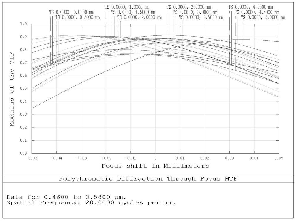
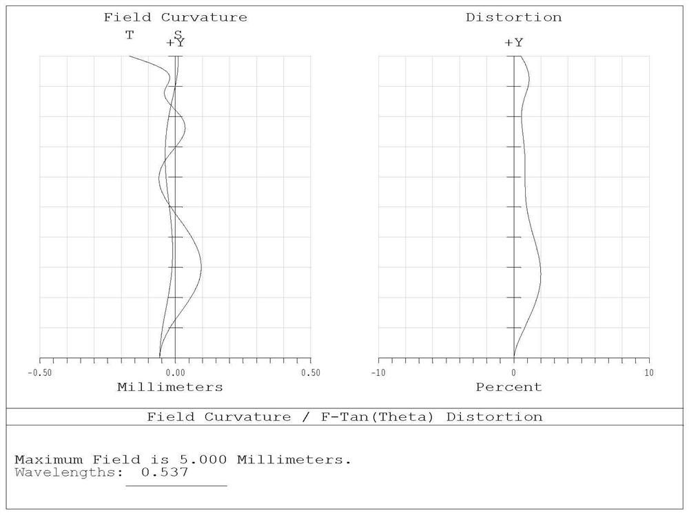

Image

  • 3P ultra-wide-angle lens
  • 3P ultra-wide-angle lens
  • 3P ultra-wide-angle lens

Examples


no. 1 example

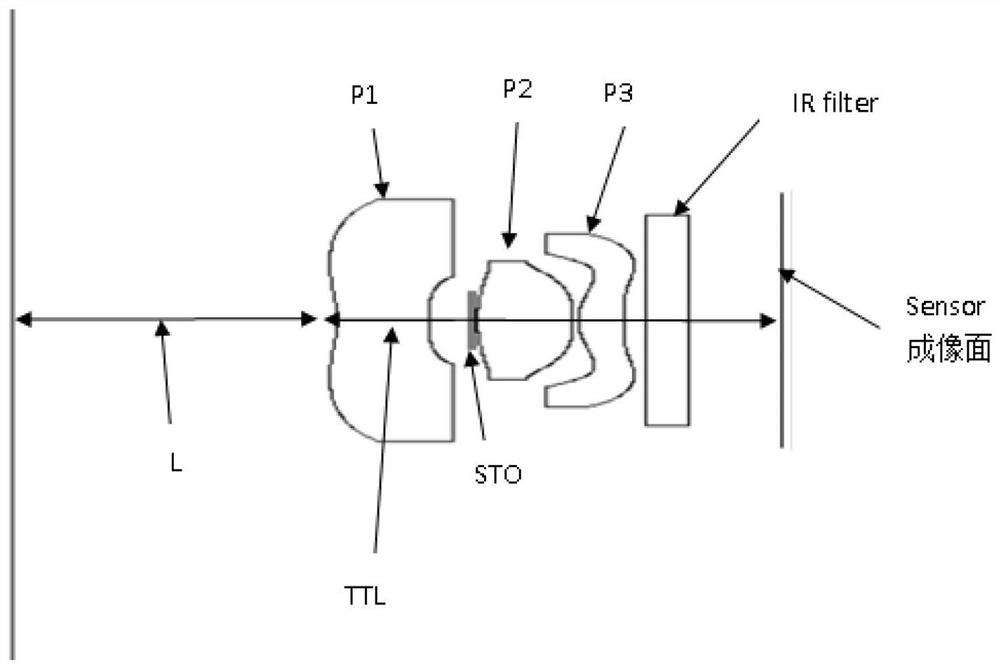
[0043] see figure 1 , figure 1 It is a 3P super wide-angle lens provided by the first embodiment of the present invention. The 3P super wide-angle lens used under the ultra-fine object distance includes: a first lens, a second lens, a third lens, a filter located on the image side of the third lens, and an imaging surface arranged sequentially from the object side to the image side , the first lens is a negative lens, the surface of the first lens close to the object side is P1R1, the center of the surface P1R1 is concave towards the object side, the surface of the first lens close to the image side is called P1R2, and the center of the surface P1R2 is convex towards the image The side edge turns concave to the image side, the second lens is a positive lens, the surface of the second lens close to the object side is P2R1, the center of the surface P2R1 is convex to the object side, and the surface of the second lens P2 close to the image side is called P2R2. The center of th...

no. 2 example

[0063] The second embodiment is a counter-example introduced.

[0064] The shape of each lens in the second embodiment is: the first lens P1 is a negative lens (the surface of P1 close to the object side is called P1R1, and its center is concave to the object side, and the surface of P1 close to the image side is called P1R2 , whose center is concave toward the image side.

[0065] The second lens P2 is a positive lens (the side of P2 near the object side is called P2R1, and its center is convex toward the object side, and the side of P2 near the image side is called P2R2, and its center is concave toward the image side, and its core Thickness is T2).

[0066] The third lens P3 is a positive lens (the surface of P3 close to the object side is called P3R1, and its center is concave toward the object side, and the side of P3 close to the image side is called P3R2, and its center is convex toward the image side).

[0067] That is, the shapes of the three lenses of the second em...


PUM


Abstract

The invention discloses a 3P ultra-wide-angle lens which comprises a first lens, a second lens and a third lens which are sequentially arranged from an object side to an image side, the first lens is a negative lens, the surface, close to the object side, of the first lens is P1R1, the center of the surface P1R1 is concave towards the object side, the surface, close to the image side, of the first lens is P1R2, the center of the surface P1R2 is convex towards the image side, when close to the edge, the lens turns to be concave towards the image side, the second lens is a positive lens, the surface, close to the object side, of the second lens is P2R1, the center of the surface P2R1 is convex towards the object side, the surface, close to the image side, of the second lens P2 is called P2R2, the center of the surface P2R2 is convex towards the image side, and the core thickness is T2. The third lens is a positive lens, the surface, close to the object side, of the third lens is P3R1, and the center of the surface P3R1 is convex towards the object side. The total focal length of the 3P ultra-wide-angle lens is f, and the ultra-wide-angle lens meets the condition that T2 / f is larger than 0.7 and smaller than 1.5.

Description

technical field [0001] The invention relates to the field of optical technology, in particular to a 3P super wide-angle lens. Background technique [0002] In the current era of advanced information, the increasing dependence on electronic products makes human beings inseparable from the convenience brought by electronic products, and thus extends the product of mobile phones. In the past, mobile phones were only used to receive messages and answer calls. The invention of the LCD screen and the development of network information make the application in the 3C industry chain more and more demand for the application of optical lens. From the initial VGA model to 2M ~ 5M ~ 8M ~ 13M, the demand for pixels is getting higher and higher. , so mobile phones have gradually replaced the application of digital cameras and become a necessity for everyone to take pictures in their lives. They have also formed the habit of writing diaries for their lives. They will take pictures of their ...

Claims


Application Information

Patent Timeline
IPC IPC(8): G02B13/00G02B13/06G02B13/18G02B13/24G02B1/04G03B30/00
CPCG02B13/0035G02B13/06G02B13/18G02B1/041G02B13/24G03B30/00
Inventor 陈俊宏
Owner HUBEI HUAXIN PHOTOELECTRIC CO LTD
Learn More