Radiation hole design method of thermal radiation component and thermal radiation component

A technology of heat radiation components and design methods, which is applied to heating elements, ohmic resistance heating components, etc., can solve the problems of inability to achieve uniform heating and difficulty in uniform heating, and achieve the effect of increasing radiation amount and uniform heating

Pending Publication Date: 2021-10-01
FOSHAN SHUNDE DISTRICT LONGZHISHENG ELECTRIC HEATING ELECTRICAL APPLIANCES
View PDF0 Cites 0 Cited by
  • Summary
  • Abstract
  • Description
  • Claims
  • Application Information

AI Technical Summary

Problems solved by technology

[0002] Traditional bread ovens and other heating cooking utensils are difficult to achieve uniform heating. The farther the distance between the radiation source and the heating surface is, the smaller the heat radiation intensity per unit area is; The color of the chip near the heating tube source is often dark and the color far away from the heating tube source is light. Although the size of the radiation hole or the heat reflection cycle has been processed in the prior art, it cannot be accurately designed due to the inability to achieve accurate size design. evenly heated

Method used


Image

  • Radiation hole design method of thermal radiation component and thermal radiation component
  • Radiation hole design method of thermal radiation component and thermal radiation component
  • Radiation hole design method of thermal radiation component and thermal radiation component

Examples


Embodiment 1

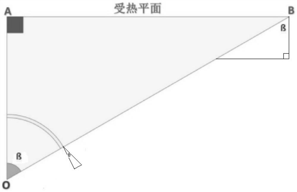
[0050] see figure 1 The schematic diagram of the design principle of the radiation hole of the heat radiation component is shown. Embodiment 1 of the present application discloses a design method of the radiation hole of the heat radiation component. The design method includes the following steps:

[0051] Step 1, mark the thermal radiation source with a point O, and mark the heated plane corresponding to the thermal radiation source with a line segment AB, wherein the heated plane is parallel to the thermal radiation source, the line segment OA is perpendicular to the line segment AB, and the The heat radiation member is arranged between the heat radiation source and the heated plane, and the heat radiation of the heat radiation source passes through the radiation holes on the heat radiation member to heat the heated plane. Preferably, in order to facilitate analysis and calculation, The heat radiation member is perpendicular to the line segment OA at OA, that is, the radiati...

Embodiment 2

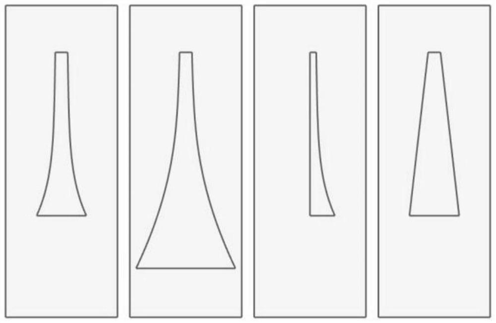
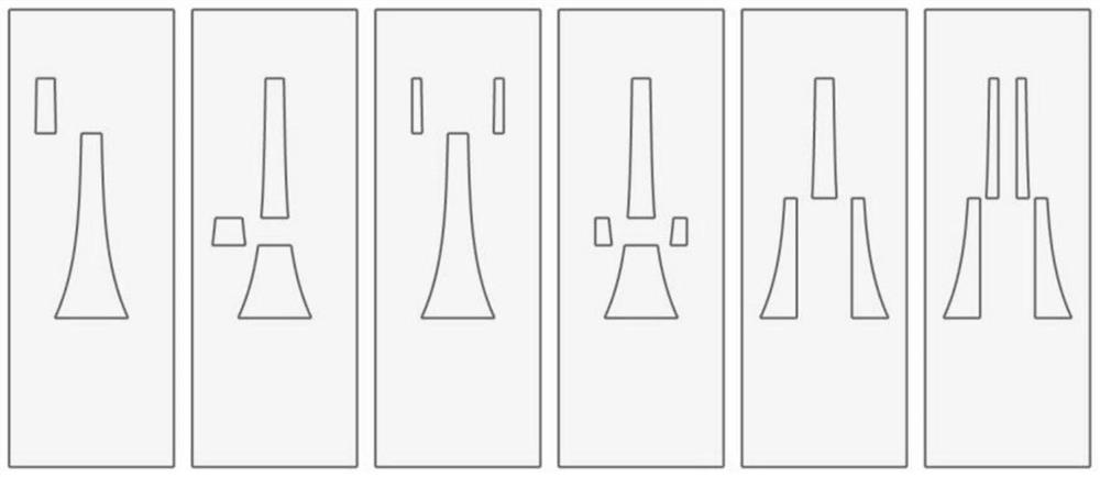
[0077] see Figure 4-7 As shown, this embodiment 2 discloses a structure of a heat radiation member, and the radiation hole of the heat radiation member is designed and manufactured using the radiation hole design method described in the above embodiment 1.

[0078] Specifically, it is assumed that the heat radiation source is marked with a point O, and the heating plane corresponding to the heat radiation source is marked with a line segment AB, and the line segment OA is perpendicular to the line segment AB, and the heat radiation member is arranged between the heat radiation source and the heating plane In between, the heat radiation rays of the heat radiation source pass through the radiation holes on the heat radiation member to heat the heated plane.

[0079] Preferably, in order to facilitate analysis and calculation, the heat radiation member is perpendicular to the line segment OA at OA, that is, the radiation line OA passes through the heat radiation member in a mann...

Embodiment 3

[0089] see Figure 8 with Figure 9 As shown, Embodiment 3 discloses a heat radiation assembly, and the heat radiation assembly includes the heat radiation member of Embodiment 2 and a heat radiation source 3, and the heat radiation source 3 is arranged inside or inside the heat radiation member .

[0090] In one embodiment, the heat radiation assembly includes side plates arranged on both sides of the heat radiation member, and the heat radiation source 3 is installed and fixed on the side plates.

[0091] Preferably, the heat radiation assembly is arranged on any one or several of the six walls of the oven, such as up, down, left, and right, and front and back, for uniform heating of the food in the oven,


PUM


Abstract

The invention discloses a radiation hole design method of a heat radiation component and the heat radiation component. The design method comprises the following steps that 1, a certain point on a heat radiation source is marked with a point O, a heated plane corresponding to the heat radiation source is marked with a line segment AB, the heated plane is parallel to the heat radiation source, a line segment OA is perpendicular to the line segment AB, the width of a radiation hole at the intersection of the line segment OA and a heat radiation component is marked with K1, and the width of a radiation hole at the intersection of a line segment OB and the heat radiation component is marked with K2; and 2, the radiation angle of the radiation line OB is beta, the deflection angle of the heat radiation component at the line segment OB is marked with theta, the relation between K1 and K2 is designed according to beta and theta, K2 is larger than K1, and all points on the heated plane are heated evenly. According to the invention, through mathematical derivation of the radiation hole, the effects of equal-intensity radiation of all points on a heated plane and uniform far and near heating are obtained.

Description

technical field [0001] The application belongs to the technical field of cooking utensils, and in particular relates to a radiation hole design method of a heat radiation component and the heat radiation component. Background technique [0002] Traditional bread ovens and other heating cooking utensils are difficult to achieve uniform heating. The farther the distance between the radiation source and the heating surface is, the smaller the heat radiation intensity per unit area is; The color of the chip near the heating tube source is often dark and the color far away from the heating tube source is light. Although the size of the radiation hole or the heat reflection cycle has been processed in the prior art, it cannot be accurately designed due to the inability to achieve accurate size design. heated evenly. Contents of the invention [0003] In view of the above problems, the present application discloses a radiation hole design method of a heat radiation component and...

Claims


Application Information

Patent Timeline
IPC IPC(8): H05B3/06
CPCH05B3/06
Inventor 廖伟创廖建东廖建维
Owner FOSHAN SHUNDE DISTRICT LONGZHISHENG ELECTRIC HEATING ELECTRICAL APPLIANCES
Why Eureka
Try Eureka