Antenna apparatus for transponder

a transponder and antenna technology, applied in the field of antenna apparatus, can solve the problems of difficult to hold the required attachment strength, antenna apparatus, manufacturing cost may not be reduced, etc., and achieve the effect of reducing height, increasing the gain of vertically polarized wave components, and high field intensity

Inactive Publication Date: 2008-11-18
ALPS ALPINE CO LTD
View PDF7 Cites 6 Cited by
  • Summary
  • Abstract
  • Description
  • Claims
  • Application Information

AI Technical Summary

Benefits of technology

[0009]The present invention provides an antenna apparatus that easily provides reduction in height of the apparatus and reduction in manufacturing cost thereof, allows the apparatus to be mounted at a wheel rim later, and efficiently radiates a vertically polarized wave toward a sidewall of a tire.
[0011]Since the antenna element mounted on the circuit board employs a structure of an inverse-F antenna, an electric field generated between the radiating conductor and the grounding conductor layer of the circuit board is radiated as a radio wave (a linearly polarized wave) having a vertically polarized wave component and a horizontally polarized wave component. Since the antenna apparatus is arranged in the resin case attached at the end portion of the air valve such that the one side surface extending in the longitudinal direction of the space defined between the circuit board and the radiating conductor faces the one of the sidewalls of the tire, the vertically polarized wave with the high field intensity is radiated from the antenna element toward the sidewall. Accordingly, the gain of the vertically polarized wave component may be increased, and the entire antenna apparatus may be reduced in height. In the antenna apparatus, since the electronic circuit portion of the circuit board is covered with the sheet-metal shield case conducting to the grounding conductor layer, the electronic circuit portion is electromagnetically shielded, whereby an erroneous operation may be prevented. In addition, the ground of the antenna element may be enhanced by the shield case, resulting in the amount of radiation of the horizontally polarized wave being decreased while the amount of radiation of the vertically polarized wave being increased. Accordingly, the antenna element of the antenna apparatus may radiate the vertically polarized wave efficiently toward the sidewall of the tire, thereby markedly improving the communication performance. Also, the antenna apparatus may be attached to various types of wheels later without the necessity of modifying the air valve to be attached. Accordingly, the manufacturing cost of the antenna apparatus may be relatively low, and usability of the antenna apparatus may be improved.
[0012]With the above configuration, the other side surface extending in the longitudinal direction of the space defined between the circuit board and the radiating conductor may preferably face a wall surface of the wheel rim with a distance interposed therebetween, the distance being about one-fourth of a wavelength of a radio wave to be used. Accordingly, the vertically polarized wave radiated toward the sidewall after it is reflected by the wall surface may be superposed with the vertically polarized wave directly radiated from the antenna element toward the sidewall, thereby further increasing the gain of the vertically polarized wave component.
[0013]With the above configuration, the antenna element may be preferably formed by sheet-metal processing. Accordingly, the antenna element with a low manufacturing cost and a high mechanical strength may be provided. In addition, in a case where the feeding conductor and the grounding conductor of the sheet-metal antenna element are formed as bent pieces extending to the circuit board from an end portion in a longitudinal direction of the radiating conductor made of a metal plate, the antenna element may serve as a typical inverse-F antenna. Alternatively, in a case where the feeding conductor and the grounding conductor are formed as bent pieces extending toward the circuit board from a center portion in a longitudinal direction of the radiating conductor made of a metal plate, an antenna element being an inverse-F antenna but having a substantially T-shaped appearance may be provided, and the radiation of the horizontally polarized wave is decreased. Accordingly, the radiation efficiency of the vertically polarized wave may be further enhanced, and the posture of the antenna element may be a markedly stable.
[0014]With the above configuration, the resin case may preferably have an attachment protrusion to be inserted and pressed to an air hole of the air valve and fixed thereto. Accordingly, the resin case may be easily and reliably attached to the end portion of the air valve.
[0015]Since the antenna apparatus of the present invention has the antenna element with the structure of the inverse-F antenna, and is arranged in the resin case attached at the end portion of the air valve such that the one side surface extending in the longitudinal direction of the space defined between the circuit board and the radiating conductor faces the one of the sidewalls of the tire, the vertically polarized wave with the high field intensity is radiated from the antenna element toward the sidewall. Accordingly, the gain of the vertically polarized wave component may be increased, and the entire antenna apparatus may be reduced in height. In the antenna apparatus, since the electronic circuit portion of the circuit board is covered with the sheet-metal shield case conducting to the grounding conductor layer, the electronic circuit portion is electromagnetically shielded, whereby an erroneous operation may be prevented. In addition, the ground of the antenna element may be enhanced by the shield case, resulting in the amount of radiation of the horizontally polarized wave being decreased while the amount of radiation of the vertically polarized wave being increased. Accordingly, the antenna element of the antenna apparatus may radiate the vertically polarized wave efficiently toward the sidewall of the tire, thereby markedly improving the communication performance. Also, the antenna apparatus may be attached to various types of wheels later without the necessity of modifying the air valve to be attached. Accordingly, manufacturing cost of the antenna apparatus may become relatively low, and usability of the antenna apparatus may be improved. Thus noticeable practical effects may be obtained.

Problems solved by technology

Thus, it is difficult to hold a required attachment strength merely by bonding the antenna apparatus on the wheel rim.
However, in these known antenna apparatuses in which the antenna apparatuses are mounted at the wheel rims by using the air valves as described above, when a configuration in which a part of an air valve (e.g., a grommet) is modified to be used for the antenna apparatus is employed, the manufacturing cost may not be reduced, and the antenna apparatus may not be attached to various types of wheels later.
Also, in these known antenna apparatuses mounted at the wheel rims, when a configuration in which the entire apparatus is not sufficiently reduced in height is employed, a tool or the like may come into contact with the antenna apparatus during detachment of a tire, whereby the apparatus may be damaged.
This may degrade communication performance.

Method used


Image

  • Antenna apparatus for transponder
  • Antenna apparatus for transponder
  • Antenna apparatus for transponder

Examples


first embodiment

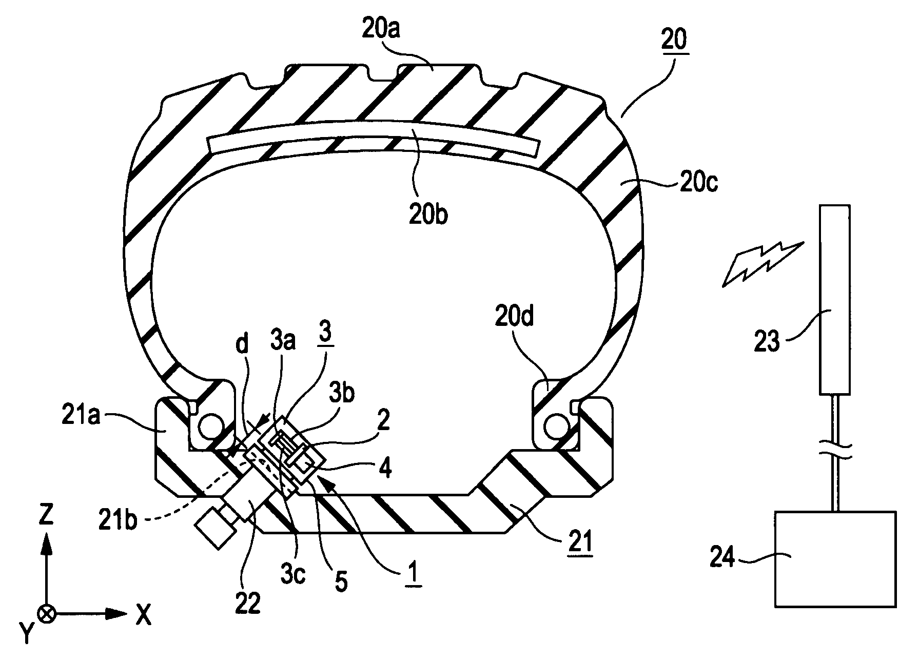
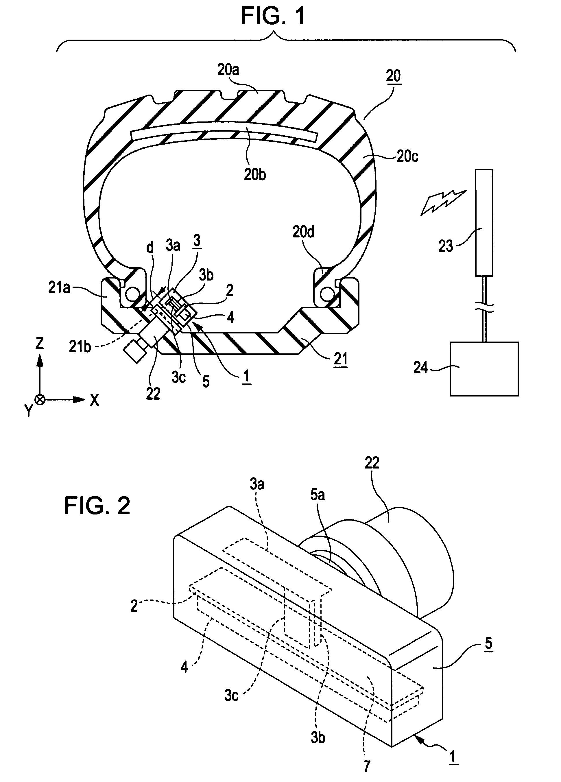
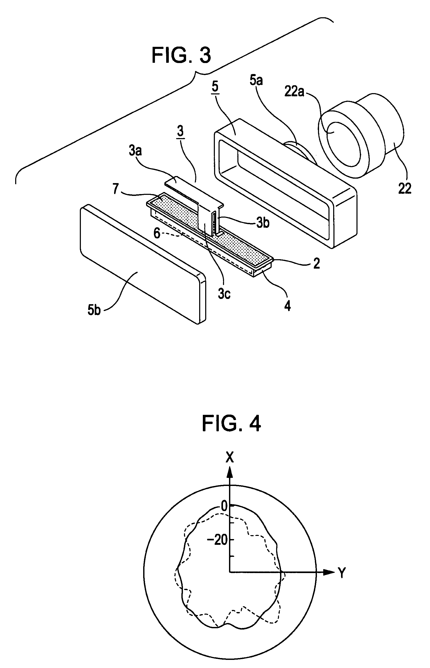
[0022]An embodiment of the present invention is described with reference to FIGS. 1 to 5. FIG. 1 is a cross-sectional view schematically showing a state where an antenna apparatus according to the present invention is mounted at a wheel rim, FIG. 2 is a perspective view specifically showing a primary portion of the antenna apparatus in an attached state, FIG. 3 is an exploded perspective view corresponding to FIG. 2, FIG. 4 is a characteristic diagram showing a radiation pattern in an azimuth plane of the antenna apparatus, and FIG. 5 is a characteristic diagram showing a radiation pattern in an elevation plane of the antenna apparatus.

[0023]An antenna apparatus 1 shown in FIGS. 1 to 3 is mounted at a wheel rim 21 at a position facing the space inside a tire 20, to be used as a transponder of a tire-pressure monitoring system (TPMS). The antenna apparatus 1 is attached by using an air valve 22 provided at the wheel rim 21. The antenna apparatus 1 is mainly composed of a circuit boar...

second embodiment

[0033]FIG. 6 is a perspective view showing an antenna apparatus according to the present invention. The same reference numerals are given to the portions corresponding to FIGS. 2 and 3, and their descriptions are omitted.

[0034]An antenna apparatus 11 shown in FIG. 6 has an antenna element 3 formed by sheet-metal processing and having a shape markedly different from that of the above-described first embodiment. In particular, in the antenna element 3 of the antenna apparatus 11, the feeding conductor 3b and the grounding conductor 3c are formed as bent pieces extending toward the circuit board 2 from a center portion in a longitudinal direction of the radiating conductor 3a made of a metal plate. The antenna element 3 is an inverse-F antenna; however, the appearance thereof is substantially T-shaped. Since the antenna element 3 is substantially T-shaped, the amount of radiation of the horizontally polarized wave is decreased, and consequently, the radiation efficiency of the vertical...


PUM


Abstract

An antenna apparatus is mounted at a wheel rim as a transponder of a system for monitoring a tire pressure or the like, and attached at an end portion of an air valve. The apparatus includes a circuit board having an electronic circuit portion and a grounding conductor layer, a sheet-metal inverse-F type antenna element, a sheet-metal shield case conducting to the grounding conductor layer to cover the electronic circuit portion, and a resin case for accommodating these components. One side surface extending in a longitudinal direction of a space defined between the circuit board and the radiating conductor of the antenna element faces one of sidewalls of a tire, and the other side surface thereof faces a wall surface of the wheel rim with a distance interposed therebetween, the distance being about one-fourth of a wavelength of a radio wave to be used.

Description

CLAIM OF PRIORITY[0001]This application claims benefit of the Japanese Patent Application No. 2006-181930 filed on Jun. 30, 2006, which is hereby incorporated by reference.BACKGROUND OF THE INVENTION[0002]1. Field of the Invention[0003]The present invention relates to an antenna apparatus mounted at a wheel rim of a tire of a vehicle, to be used as a transponder of a system for monitoring a tire pressure or the like.[0004]2. Description of the Related Art[0005]In recent years, systems for monitoring tire pressures have been popular. In such a system, an antenna apparatus with a pressure sensor like a quartz vibrator embedded is mounted at a rim of a wheel (a wheel rim) of a tire, so that a driver can recognize a tire pressure even while driving the vehicle. In the tire-pressure monitoring system (TPMS), the antenna apparatus used as a transponder is generally attached to the wheel rim at a side facing the space inside the tire. Such an antenna apparatus has an antenna element capabl...

Claims


Application Information

Patent Timeline
Patent Type & Authority Patents(United States)
IPC IPC(8): H01Q1/42
CPCH01Q1/2241H01Q9/0421B60C23/0494
Inventor SHIGIHARA, MAKOTOKONNO, YASUHIRO
Owner ALPS ALPINE CO LTD
Why Eureka
Try Eureka