Quilt kicking-prevention device for pediatric department

An anti-kick and pediatric technology, applied in the field of medical devices, can solve the problems of high temperature, the quilt is propped up, and the hot air cannot be discharged in time, so as to achieve the effect of rapid cooling, lowering the temperature, and maintaining high-quality sleep.

Active Publication Date: 2021-10-08
QINGDAO WOMEN & CHILDREN HOSPITAL
View PDF9 Cites 0 Cited by
  • Summary
  • Abstract
  • Description
  • Claims
  • Application Information

AI Technical Summary

Problems solved by technology

[0003] The purpose of the present invention is to solve the problem that the existing anti-kick quilt device in the prior art makes it difficult for children to prop up the quilt, resulting in the hot air in the quilt not being discharged in time, so that the temperature in the quilt is high, and it is difficult for children to move around with high quality. A Pediatric Anti-Kicking Device Proposed

Method used


Image

  • Quilt kicking-prevention device for pediatric department
  • Quilt kicking-prevention device for pediatric department
  • Quilt kicking-prevention device for pediatric department

Examples


Embodiment 1

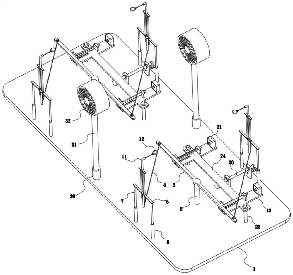
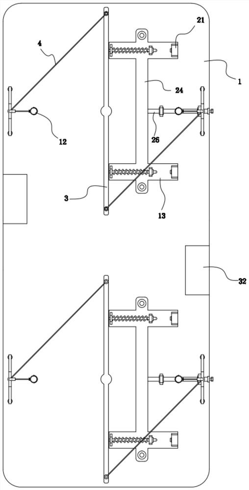
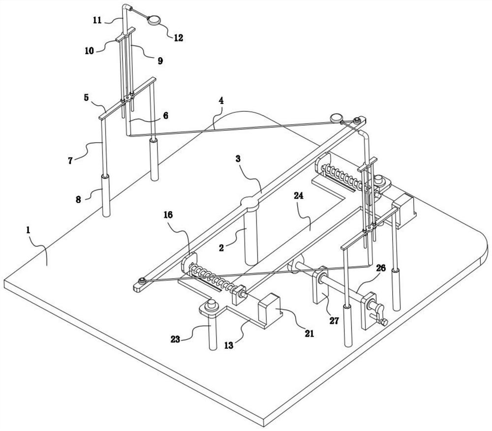
[0024] refer to Figure 1-8 , a pediatric anti-kicking device, comprising a base 1, the upper surface of the base 1 is rotatably installed along its length direction with two correspondingly arranged rotating shafts 2, and a cross bar 3 is fixedly installed on the top of the two rotating shafts 2, each One end of a stay rope 4 is respectively fixed at both ends of the cross bar 3, and a stay rope guide mechanism is fixedly installed on the upper surface of the base 1 on both sides of each rotating shaft 2, and the stay rope guide mechanism is set in one-to-one correspondence with the stay rope 4, One end of each stay cord 4 is fixedly installed with a quilt fixer after passing through the corresponding stay cord guide mechanism, and each cross bar 3 side is all provided with a position-limiting mechanism corresponding thereto.

[0025] The stay cord guiding mechanism includes a first horizontal plate 5, a first guide tube 6, an insertion column 7, a first insertion socket 8, a...

Embodiment 2

[0030] refer to Figure 1-8 , as another preferred embodiment of the present invention, the difference from Embodiment 1 is that a corresponding delay power-off switch 21 is fixedly installed on the supporting plate 13 outside each rubber head 18, and the delay power-off switch 21 The switch 21 is provided with a button 22 corresponding to the rubber head 18, so that the rubber head 18 can press the button 22 on the adjacent power-delay switch 21; the power-delay switch 21 can be freely set to extend the time, When the button 22 is pressed, the power-delay switch 21 will be turned on, and after keeping the on state for a period of time, it will be turned off, and the button 22 will be reset automatically.

[0031] An electric fan module is fixedly installed on both sides of the upper surface of the base 1 between the two rotating shafts 2. The two electric fan modules are arranged in a staggered manner. Both electric fan modules are electrically connected to the same power sup...


PUM


Abstract

The invention relates to the technical field of medical instruments, in particular to a quilt kicking-prevention device for pediatric department, which comprises a base, two rotating shafts which are correspondingly arranged are rotatably mounted on the upper surface of the base in the length direction of the base, a cross rod is fixedly mounted at the top end of each rotating shaft, and one end of a pull rope is fixed to each of the two ends of each cross rod. The upper surface of the base on the two sides of each rotating shaft is fixedly provided with a pull rope guiding mechanism, the pull rope guiding mechanisms and pull ropes are arranged in a one-to-one correspondence mode, one end of each pull rope penetrates through the corresponding pull rope guiding mechanism and then is fixedly provided with a quilt fixing device, and one side of each transverse rod is provided with a limiting mechanism corresponding to the corresponding cross rod. The quilt can be prevented from being kicked off, and hot air in the quilt can be exhausted quickly, so that children can have high-quality sleep.

Description

technical field [0001] The invention relates to the technical field of medical devices, in particular to a pediatric anti-kicking device. Background technique [0002] In the Department of Pediatrics of the hospital, some children may kick off the quilt during the night rest. Some children with weak physique are prone to catch cold and endanger their health. For some children who are in the process of treatment, Undoubtedly, it will add a lot of trouble to the normal treatment process. The main reason for children to kick the quilt is generally that the child's body feels that the temperature in the quilt is too high and feels hot, so that the quilt is involuntarily propped up with legs and feet, so that there is a gap between the quilt and the bed body, so that The hot air in the quilt can leak out, and then realize the cooling of the inside of the quilt to make oneself feel comfortable. After the temperature drops, the legs and feet will be retracted to make the quilt fit...

Claims


Application Information

Patent Timeline
Patent Type & Authority Applications(China)
IPC IPC(8): A47D15/02A47D15/00F04D25/08F04D25/16F04D27/00
CPCA47D15/02A47D15/00F04D25/08F04D25/166F04D27/008F04D27/00
Inventor 不公告发明人
Owner QINGDAO WOMEN & CHILDREN HOSPITAL
Why Eureka
Try Eureka