Gas flowing mixing device

A technology of gas flow and hole insertion, applied in the direction of mixing methods, dissolution, chemical instruments and methods, etc., can solve the problems of complicated equipment, cumbersome process, poor mixing control ability, etc., to simplify working equipment, reduce demand, increase efficiency effect

Pending Publication Date: 2021-10-08
申婷
View PDF5 Cites 0 Cited by
  • Summary
  • Abstract
  • Description
  • Claims
  • Application Information

AI Technical Summary

Problems solved by technology

[0002] At present, for the gas mixing device, especially the main gas, in order to achieve a better chemical effect, a certain proportion of auxiliary gas needs to be mixed. When the existing mixing device is mixed, the equipment relied on is relatively complicated, and the process is also relatively cumbersome. For mixing control Poor ability

Method used


Image

  • Gas flowing mixing device
  • Gas flowing mixing device
  • Gas flowing mixing device

Examples


Embodiment Construction

[0013] The following will clearly and completely describe the technical solutions in the embodiments of the present invention with reference to the accompanying drawings in the embodiments of the present invention. Obviously, the described embodiments are only some, not all, embodiments of the present invention. Based on the embodiments of the present invention, all other embodiments obtained by persons of ordinary skill in the art without making creative efforts belong to the protection scope of the present invention.

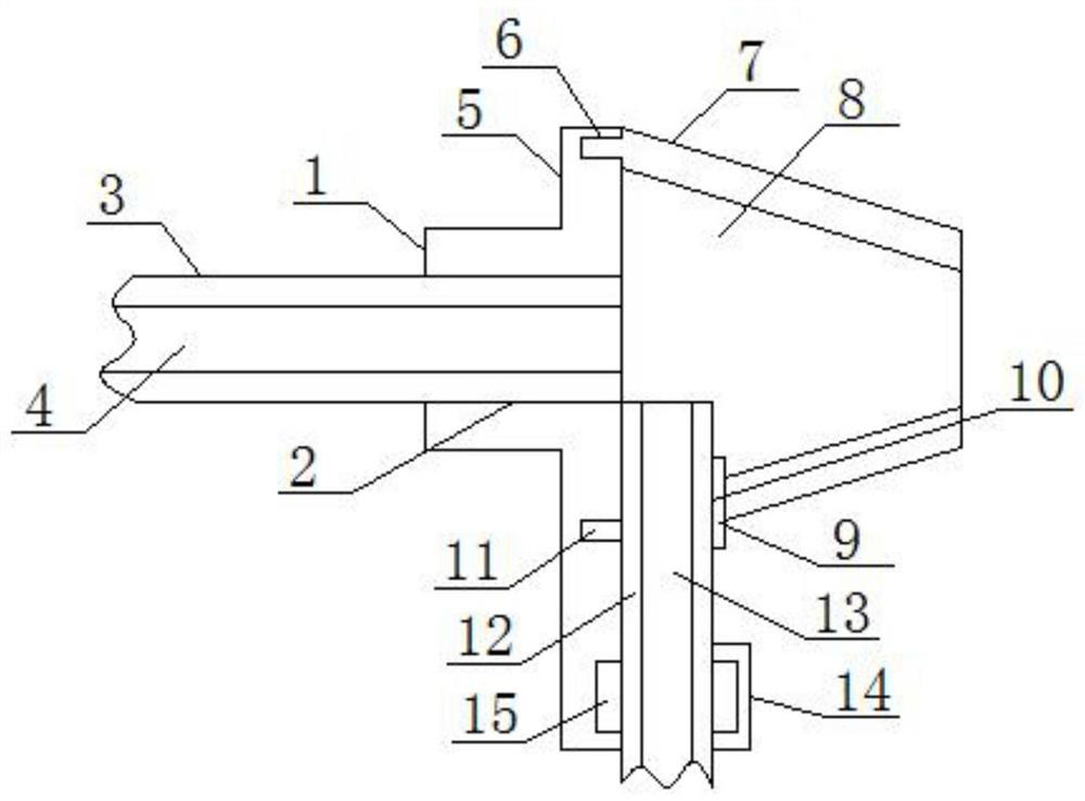
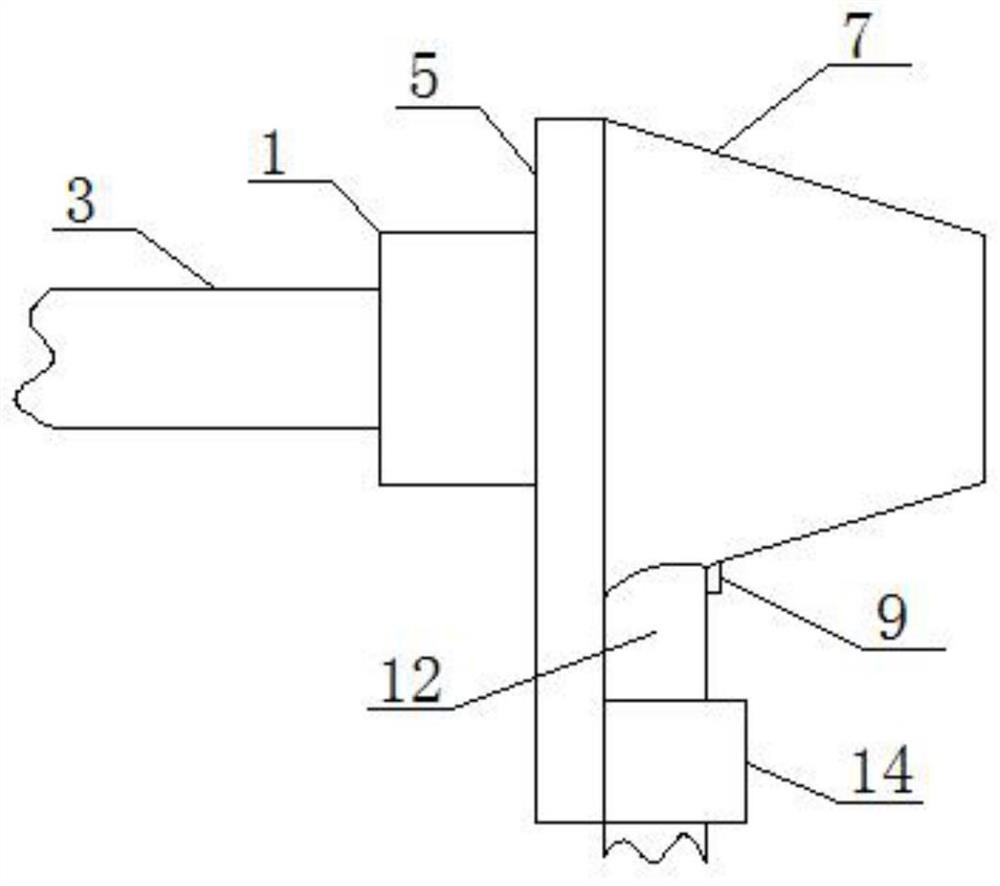
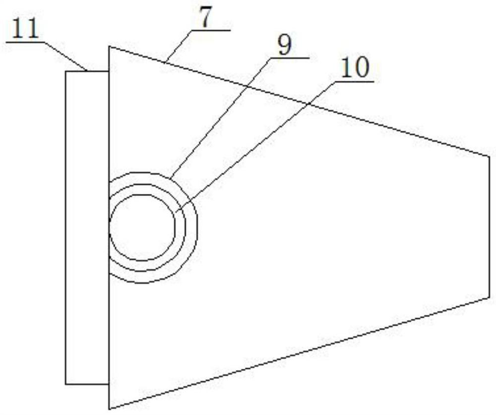
[0014] see Figure 1-3 , an embodiment provided by the present invention: including a pipe sleeve shell 1, a main air intake pipe 3 and a secondary air intake pipe 12 with a secondary air intake hole 13 in the center, and one end of the pipe sleeve shell 1 is provided with an integrated structure The vertical flat plate 5 of the pipe socket casing 1 is provided with a main pipe installation hole 2 connected to its two ends, and a main air intake pipe 3 is inst...


PUM


Abstract

The invention discloses a gas flowing mixing device, comprising a pipeline sleeving shell, a main gas inlet pipeline and an auxiliary gas inlet pipeline with an auxiliary gas inlet hole in the center. According to the invention, aerodynamics is utilized; that is, the higher a flowing speed is in an area, the lower the air pressure nearby the area is; main air is rapidly discharged, so the air pressure of the main air nearby a discharging part is reduced, auxiliary gas can flow into the discharging part of main gas under the action of atmospheric pressure, and the auxiliary gas and the main gas can be mixed; due to the fact that aerodynamics is utilized by the device, the auxiliary gas does not need other extra energy sources for driving emission, the degree of the requirement for equipment during emission is reduced, and working equipment is simplified; and in addition, by changing the spatial form of the main gas in an ejection area, mixing of external useless gas can be reduced, so more negative pressure acts on the sucked auxiliary gas, the effective utilization rate of the sucked auxiliary gas is improved, the efficiency of the auxiliary gas is improved, and controllability is achieved.

Description

technical field [0001] The invention relates to the technical field of gas mixing, in particular to a gas flow mixing device. Background technique [0002] At present, for the gas mixing device, especially the main gas, in order to achieve a better chemical effect, a certain proportion of auxiliary gas needs to be mixed. When the existing mixing device is mixed, the equipment relied on is relatively complicated, and the process is also relatively cumbersome. For mixing control The ability is relatively poor. Contents of the invention [0003] The purpose of the present invention is to provide a gas flow mixing device to solve the problems raised in the background art above. [0004] In order to achieve the above object, the present invention provides the following technical solutions: a gas flow mixing device, including a pipe socket shell, a main air intake pipe and a secondary air intake pipe with a secondary air inlet hole in the center, and one end of the pipe socket ...

Claims


Application Information

Patent Timeline
Patent Type & Authority Applications(China)
IPC IPC(8): B01F3/02B01F23/10
Inventor 申婷
Owner 申婷
Why Eureka
Try Eureka