Thin-specification strip steel shearing method

A thin-gauge, strip-steel technology, applied in rolling mill control devices, metal rolling, manufacturing tools, etc., can solve the problem that strips cannot be threaded, and achieve the effect of reducing manual intervention, high efficiency, easy and safe operation

Pending Publication Date: 2021-10-08
SHOUGANG ZHIXIN QIAN AN ELECTROMAGNETIC MATERIALS CO LTD
View PDF7 Cites 0 Cited by
  • Summary
  • Abstract
  • Description
  • Claims
  • Application Information

AI Technical Summary

Problems solved by technology

[0004] In order to solve the above-mentioned technical problems, the present invention provides a thin-gauge steel strip shearing method, which successfully removes the over-thick section, simplifies the original rolling process, and eliminates the need for manual intervention in secondary wear due to improper shearing. The step of the strip also solves the technical problem that the strip can not be threaded due to the thinner strip, reducing the operator's manual intervention in the rolling mill area

Method used


Image

  • Thin-specification strip steel shearing method
  • Thin-specification strip steel shearing method
  • Thin-specification strip steel shearing method

Examples


Embodiment 1

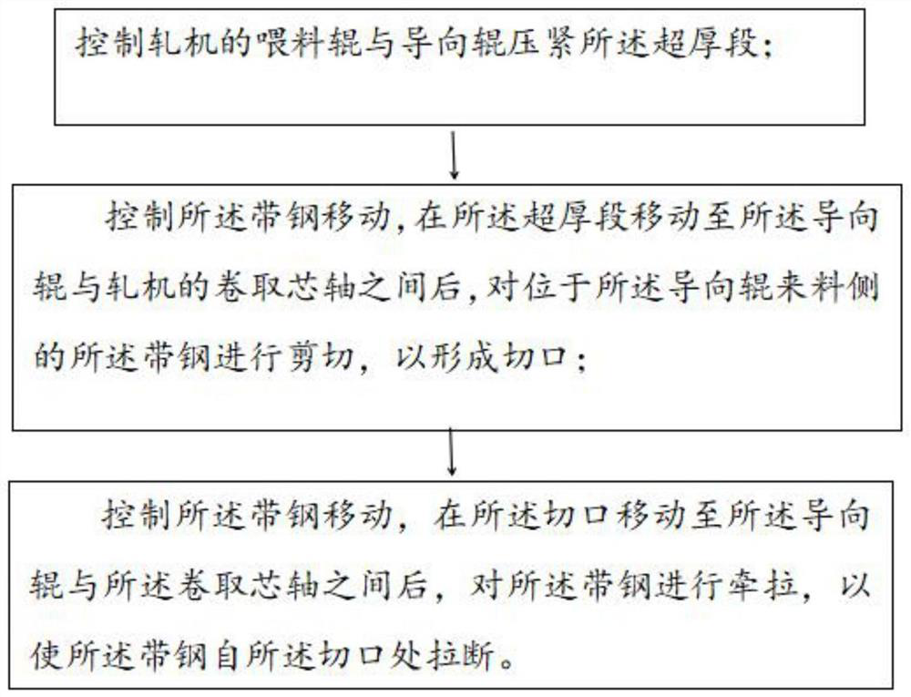
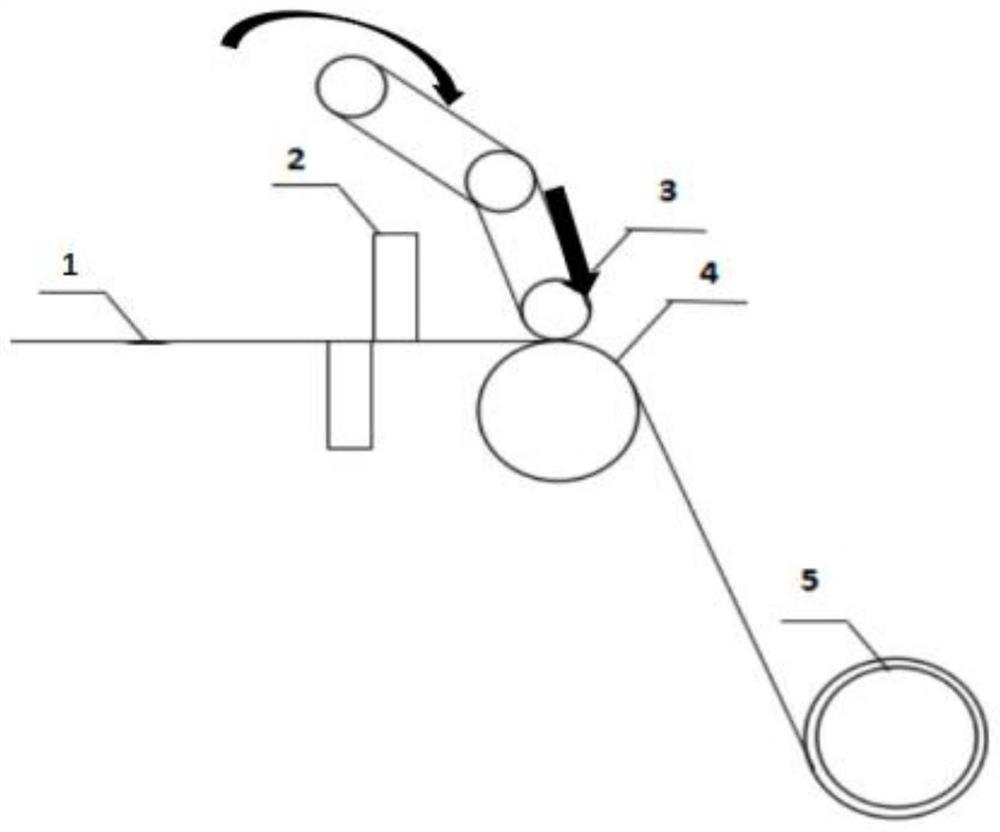
[0035] A thin-gauge strip shearing method provided by the present invention is used for shearing the ultra-thick section at one end of the strip 1 before the finished product pass of the single-stand reversing rolling mill unit rolling, and the thickness of the ultra-thick section is Exceeding the set thickness, in this embodiment, it is stipulated that the thickness of the ultra-thick section exceeds the set thickness of the previous rolling pass, including the following steps:

[0036] The feeding roller 3 and the guide roller 4 are controlled to press the super-thick section, and the strip steel 1 moves under the linkage of the coiling mandrel 5, the guide roller 4 and the feeding roller 3 to complete rolling and coiling and feeding.

[0037] Control the movement of the strip steel 1, and the strip steel 1 is coiled under the condition of linkage of various equipments. After the ultra-thick section moves between the guide roller 4 and the coiling mandrel 5 of the rolling mil...

Embodiment 2

[0049] Based on the same inventive concept, this embodiment provides a control device, which includes a memory and a processor connected to the memory. The memory stores program codes, and the processor is used to read the program codes from the memory to execute the above-mentioned embodiment 1. In the thin-gauge steel strip shearing method, the control equipment can specifically be a PLC controller, an industrial computer, and the like. In this embodiment, an industrial computer is used.

Embodiment 3

[0051] Based on the same inventive concept, this embodiment provides a computer-readable storage medium, the computer-readable storage medium stores program codes, and when the program codes are executed by a processor, the thin-gauge strip steel shears of the above-mentioned embodiment 1 can be implemented. cut method.

[0052] Through the above-mentioned embodiments, the thin-gauge steel strip shearing method provided by the present invention has the following beneficial effects or advantages:

[0053] 1) Compared with the prior art, the thin-gauge strip shearing method provided by the present invention is realized based on the structure of the rolling mill unit itself, and the slit is threaded through the strip through the linkage operation of the rolling mill and sent between the guide roll and the coiling mandrel. Under the cooperation of the coiling force of the crimping mandrel, the friction force of the guide roller and the feeding roller on the strip steel, the incisi...


PUM


Abstract

The invention discloses a thin-specification strip steel shearing method. According to the thin-specification strip steel shearing method, an end of strip steel is provided with an ultra-thick section, and the thickness of the ultra-thick section exceeds a set thickness. The thin-specification strip steel shearing method comprises the following steps: controlling a feeding roller and a guide roller of a rolling mill to press the ultra-thick section; controlling the strip steel to move, and after the ultra-thick section moves to the position between the guide roller and a curling mandrel of the rolling mill, shearing the strip steel located on the feeding side of the guide roller to form a notch; and controlling the notch to move, and after the notch moves to the position between the guide roller and the mandrel, pulling the strip steel so that the strip steel can be pulled apart from the notch. The problem of secondary strip penetrating caused by improper shearing is avoided while shearing of the ultra-thick section of the strip steel is achieved, the technical problem that strip penetrating cannot be achieved due to the fact that the strip steel is thin is solved, and manual intervention of operators entering a rolling mill area is reduced.

Description

technical field [0001] The invention relates to the technical field of metal material processing, in particular to a thin gauge strip steel shearing method. Background technique [0002] Before the rolling process of the finished product pass in the single-stand reversing mill unit, when the tail of the super-thick section does not enter the gap between the guide roll and the feed roll, it is necessary to cut the strip steel and segment the strip steel to remove the super-thick section. Thick section, keep the strip that meets the thickness requirements, the shearing operation leads to the generation of a new strip head, so the strip head needs to be threaded twice. [0003] When the rolled steel strip is thin-gauge steel strip (it is generally considered that the strip steel with a thickness below 0.5mm is a thin-gauge steel strip), it is necessary to manually cooperate with the rolling mill to pass the strip head of the thin-gauge steel strip through the feeding roller are...

Claims


Application Information

Patent Timeline
Patent Type & Authority Applications(China)
IPC IPC(8): B21B15/00B21B39/34B21B37/00
CPCB21B15/0007B21B39/34B21B37/00B21B2015/0057
Inventor 刘晓强窦世伟程智慧王建刘云霞李运来苗贺武
Owner SHOUGANG ZHIXIN QIAN AN ELECTROMAGNETIC MATERIALS CO LTD
Why Eureka
Try Eureka