Continuous stamping device for stainless steel sleeves

A stamping device and stainless steel sleeve technology, applied in the field of stamping devices, can solve problems such as low efficiency, cumbersome multi-point control, high cost of human resources, etc., and achieve the effect of ensuring accuracy

Pending Publication Date: 2021-10-08
威海华飞渔具有限公司
View PDF9 Cites 1 Cited by
  • Summary
  • Abstract
  • Description
  • Claims
  • Application Information

AI Technical Summary

Problems solved by technology

[0002] At present, stainless steel sleeves are generally stamped and formed by multiple processes at intervals, that is, the forming of a stainless steel sleeve generally requires at least three punches and corresponding workers to complete the corresponding process. The above-mentioned processing methods are obviously inefficient and the cost of human resources is high;
[0003] Secondly, at present, multiple stamping and punching at intervals can be realized through one punching machine. Although resource costs can be reduced, it only needs to cooperate with a single punching machine and a transmission mechanism to realize punching at intervals. In addition, the positioning device needs to be controlled separately, but multi-point control More cumbersome, if the above functions are realized through a driving device, its control will be greatly simplified

Method used


Image

  • Continuous stamping device for stainless steel sleeves
  • Continuous stamping device for stainless steel sleeves
  • Continuous stamping device for stainless steel sleeves

Examples


Embodiment Construction

[0027] The following will clearly and completely describe the technical solutions in the embodiments of the present invention with reference to the accompanying drawings in the embodiments of the present invention. Obviously, the described embodiments are only some, not all, embodiments of the present invention.

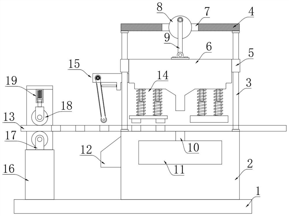
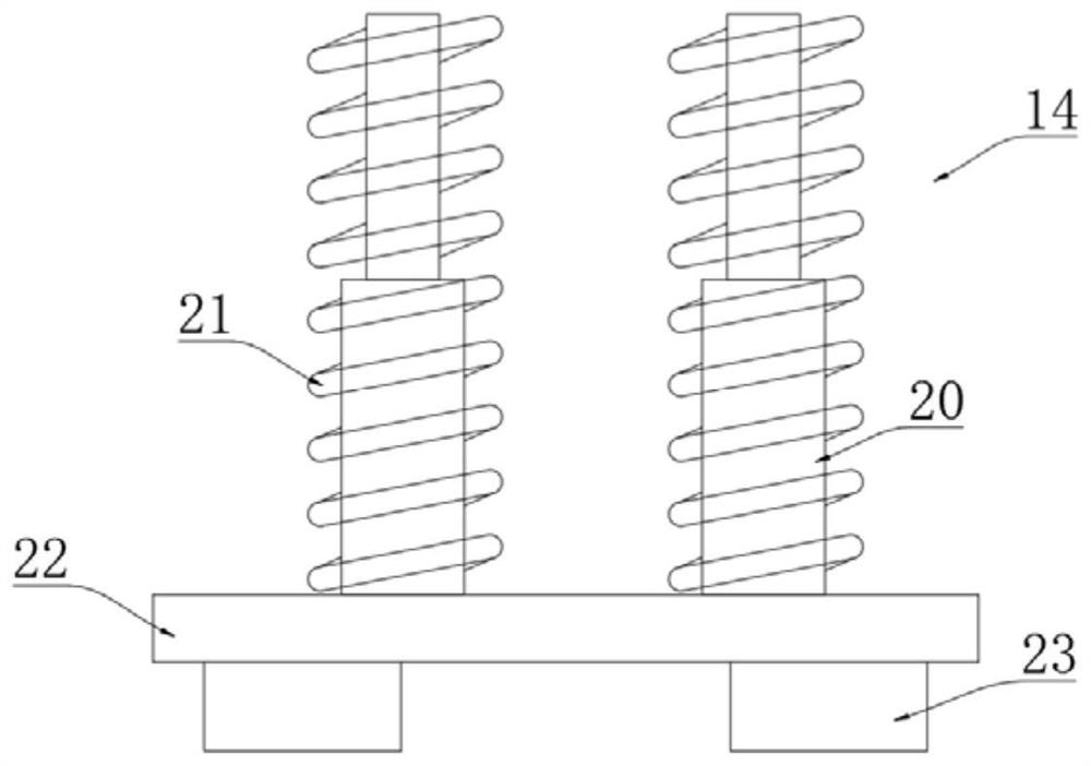
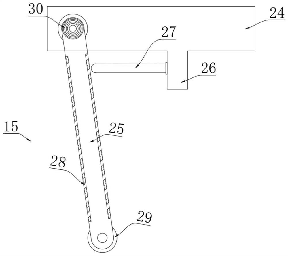
[0028] refer to Figure 1-5 , a stainless steel sleeve continuous stamping device, comprising a base 1, a support platform 2 is fixedly connected to the base 1, four guide columns 3 are fixedly connected to the support platform 2, and a connecting plate 4 is fixedly connected to the upper ends of the four guide columns 3 , The rear side of connecting plate 4 is equipped with decelerating motor, and the shaft end of decelerating motor runs through connecting plate 4 and rotates with it, and then the shaft end is coaxially fixedly connected with circular plate 8.

[0029] The connection plate 4 is installed with a through groove 7 up and down, and the circular plate 8 ...


PUM


Abstract

The invention discloses a continuous stamping device for stainless steel sleeves, which comprises a base, a supporting table is fixedly connected to the base, four guide columns are fixedly connected to the supporting table, the upper ends of the four guide columns are jointly and fixedly connected with a connecting plate, a through groove is formed in the connecting plate in an up-down penetrating mode, a circular plate is rotationally connected into the through groove, a driving rod is eccentrically hinged to the front side wall of the circular plate, the four guide columns are sleeved with guide sleeves, the four guide sleeves are jointly and fixedly connected with a stamping die head, the driving rod is hinged to the upper end of the stamping die head, and a collecting groove is formed in the supporting table in a front-back penetrating mode. The stamping work of the stamping die head can be controlled through stepping of the driving device, meanwhile, equal-distance conveying of stainless steel bands can be achieved, then equal-distance stamping can be conducted on the stainless steel bands, the stainless steel bands in the stamping process can be limited, and the stamping accuracy is guaranteed.

Description

technical field [0001] The invention relates to the technical field of punching devices, in particular to a continuous punching device for stainless steel sleeves. Background technique [0002] At present, stainless steel sleeves are generally stamped and formed by multiple processes at intervals, that is, the forming of a stainless steel sleeve generally requires at least three punches and corresponding workers to complete the corresponding process. The above-mentioned processing methods are obviously inefficient and the cost of human resources is high; [0003] Secondly, at present, multiple stamping and punching at intervals can be realized through one punching machine. Although resource costs can be reduced, it only needs to cooperate with a single punching machine and a transmission mechanism to realize punching at intervals. In addition, the positioning device needs to be controlled separately, but multi-point control Comparing loaded down with trivial details, if real...

Claims


Application Information

Patent Timeline
Patent Type & Authority Applications(China)
IPC IPC(8): B21D28/04B21D28/34B21D43/02B21D43/09B21D28/00
CPCB21D43/09B21D28/34B21D28/04B21D28/002B21D43/028
Inventor 郑新见柳洪艳郑京威
Owner 威海华飞渔具有限公司
Why Eureka
Try Eureka