Automatic press-fitting device for ball head and ball socket lantern ring assembly of engine
A press-fitting device and engine technology, applied in metal processing equipment, metal processing, manufacturing tools, etc., can solve the explosion of ball sockets and ferrules, cannot 100% guarantee the consistency and accuracy of ball head and ball socket ferrule assemblies, Problems such as low efficiency of manual inspection can achieve the effect of reducing press-fitting and inspection personnel, reducing operating costs and risks, and improving inspection accuracy.
- Summary
- Abstract
- Description
- Claims
- Application Information
AI Technical Summary
Problems solved by technology
Method used
Image
Examples
Embodiment 1
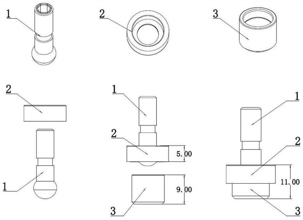
[0027] refer to Figure 1-9 , an automatic press-fitting device for an engine ball joint collar assembly, comprising a ball joint collar assembly and a ball joint collar assembly, the ball joint collar assembly is composed of a ball stud 1 and a collar 2, and the ball joint sleeve The ring assembly is composed of a ball stud 1, a collar 2 and a ball socket 3. In the ball stud collar assembly, the collar 2 has a hole in the middle on both sides, and the ball head of the ball stud 1 cannot pass through the small hole, and the ball head of the large hole can. pass.
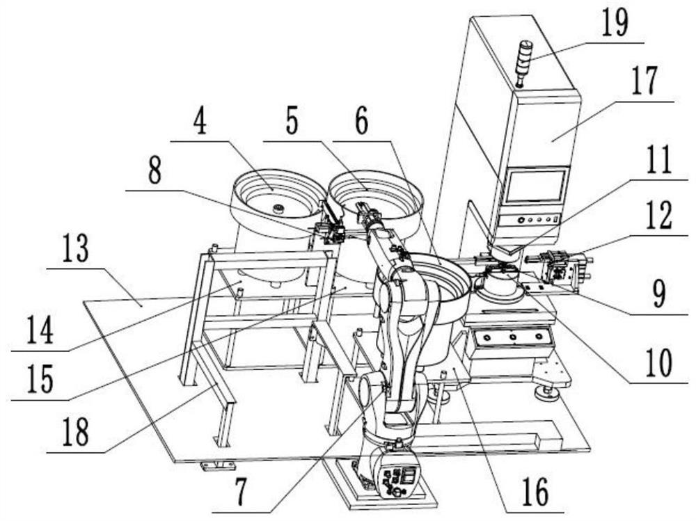
[0028] In the ball joint and socket collar assembly, the large hole of the collar 2 and the outer diameter of the opening of the ball socket 3 are in clearance fit, and the ball stud 1 can swing freely in the ball joint and socket collar assembly without stagnation. It also includes a ball head vibrating plate 4, a ring vibrating plate 5, a ball socket vibrating plate 6, a loading and unloading robot 7, a ball head ...
Embodiment 2
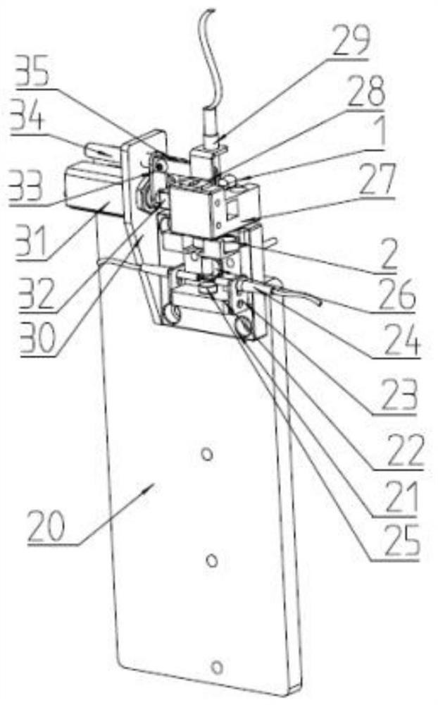
[0030] refer to Figure 1-9 , as another preferred embodiment of the present invention, the difference from Embodiment 1 is that it includes a bolt guide rail mounting plate 20, a collar positioning block mounting plate 21, a collar positioning block 22, an infrared radiation sensor mounting frame 23, and a bolt guide rail The mounting plate 20 is fixed on the upper side of the ball collar assembly fixed bracket 18 by bolts, the collar positioning block mounting plate 21 is fixed on the upper side of the bolt guide rail mounting plate 20 by bolts, and the collar positioning block 22 is fixed on the collar positioning block by bolts. On one side of the plate 21, the infrared beam sensor mounting frame 23 is fixed on both sides below the collar positioning block 22 by bolts, and the ball head is not assembled in place. The ball stud magnet 25 is adsorbed on the middle and lower end of the collar positioning block mounting plate 21, and is in the middle of the infrared sensor 24 ...
PUM
 Abstract
Description
Claims
Application Information
 - R&D
- Intellectual Property
- Life Sciences
- Materials
- Tech Scout
- Unparalleled Data Quality
- Higher Quality Content
- 60% Fewer Hallucinations
Browse by: Latest US Patents, China's latest patents, Technical Efficacy Thesaurus, Application Domain, Technology Topic, Popular Technical Reports.
© 2025 PatSnap. All rights reserved.Legal|Privacy policy|Modern Slavery Act Transparency Statement|Sitemap|About US| Contact US: help@patsnap.com


