Automatic tightening machine for OBJ (outer pull rod of steering gear)
A technology of external tie rods and tightening machines, which is applied in the direction of metal processing equipment, metal processing, manufacturing tools, etc., can solve the problems of long assembly time, low reliability, and inability to meet automatic production, so as to save labor costs, operate accurately and quickly, The effect of improving assembly efficiency and reliability
- Summary
- Abstract
- Description
- Claims
- Application Information
AI Technical Summary
Problems solved by technology
Method used
Image

Examples
Embodiment Construction
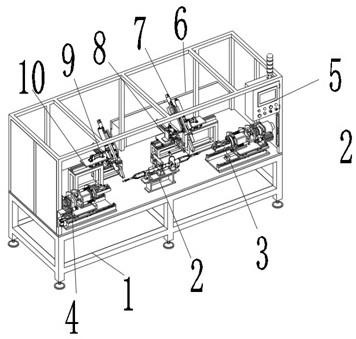
[0014] refer to figure 1 As shown, the OBJ (steering gear outer tie rod) automatic tightening machine consists of a frame 1, a clamp mechanism 2, a right pull rod tightening mechanism 3, a left pull rod tightening mechanism 4, a touch screen control panel 5, a PLC electrical control box 6, and a right nut tightening mechanism 7 , right tie rod righting mechanism 8, left tie rod righting mechanism 9 and left nut tightening mechanism 10 are formed. The fixture mechanism 2, the right tie rod tightening mechanism 3, the left tie rod tightening mechanism 4, the right nut tightening mechanism 7, the right tie rod righting mechanism 8, the left tie rod righting mechanism 9 and the left nut tightening mechanism 10 are respectively connected with the frame 1 by bolts; the right tie rod The tightening mechanism 3 and the left pull rod tightening mechanism 4 are respectively connected with the touch screen control panel 5 and the PLC electrical control box 6 through data lines; the right...
PUM
 Abstract
Description
Claims
Application Information
 - R&D
- Intellectual Property
- Life Sciences
- Materials
- Tech Scout
- Unparalleled Data Quality
- Higher Quality Content
- 60% Fewer Hallucinations
Browse by: Latest US Patents, China's latest patents, Technical Efficacy Thesaurus, Application Domain, Technology Topic, Popular Technical Reports.
© 2025 PatSnap. All rights reserved.Legal|Privacy policy|Modern Slavery Act Transparency Statement|Sitemap|About US| Contact US: help@patsnap.com