
Automatic scrap recovery device and recovery process

An automatic recovery and crushing technology, which is applied in the direction of plastic recycling, recycling technology, fixed filter element filter, etc., can solve the problems of complicated recycling device and process, and impurities in plastic particles, and achieve the effect of ensuring cleanliness and dehydration

Active Publication Date: 2021-10-08
湖南安福环保科技股份有限公司
View PDF9 Cites 1 Cited by
  • Summary
  • Abstract
  • Description
  • Claims
  • Application Information

AI Technical Summary

Problems solved by technology

[0002] Now the recycled waste plastics need to be cleaned many times through the pool, so that the impurities on the waste plastics are cleaned, and then the cleaned plastics are recycled and granulated again by melting granulation. The company's previous waste plastic cleaning At this time, the waste plastics are mainly cleaned through the ring-shaped cleaning pool, and then the waste plastics cleaned in the cleaning pool are raked out through the roller with rake nails. This semi-automatic mechanical roller realizes the separation between the plastic and the cleaning pool The liquid is separated, but the above method has a big disadvantage, that is, when the cleaned plastic is pulled out by the roller, there is still a lot of water in the waste plastic, because the water in the cleaning tank cleans the waste. Plastic, so there are more dregs in the water, if there is water in the waste plastic, there will be dregs after the sewage is dried in the waste plastic, and the waste plastic has not been cleaned, so when granulating, it will lead to plastic particles There are impurities on it; at the same time, when the roller separates the plastic in the cleaning tank, there is more water in the waste plastic on the roller, so a drying device is needed to dry the waste plastic, so that the recycling device and process become complex

Method used


Image

  • Automatic scrap recovery device and recovery process
  • Automatic scrap recovery device and recovery process
  • Automatic scrap recovery device and recovery process

Examples


Embodiment Construction

[0014] Now in conjunction with accompanying drawing, the present invention is further elaborated.

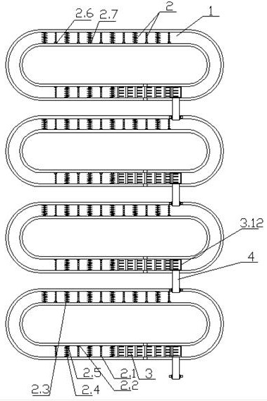
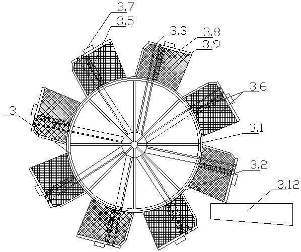
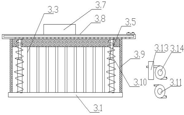
[0015] like Figure 1-3 As shown, an automatic recovery device for fines includes a cleaning tank 1, a cleaning liquid diversion mechanism 2, a scum collecting rolling screen 3 and a fines dehydration mechanism 3.6, wherein each cleaning tank 1 is an annular cleaning tank 1, and the cleaning tank 1 is a plurality of cleaning tanks 1 arranged side by side in sequence, and a cleaning liquid guide mechanism 2 is installed in each cleaning tank 1 by means of bearing fixing, and the cleaning liquid guide mechanism 2 supplies water and sprays to the cleaning tank 1 In this way, the waste plastics in the cleaning tank 1 are cleaned through the cleaning liquid guiding mechanism 2, that is, the cleaning liquid sprayed out by the cleaning liquid guiding mechanism 2 is used to wash the waste plastics, and the cleaning liquid guiding mechanism 2 can also assist in cleaning. The water flow ...


PUM


Abstract

The invention discloses an automatic scrap recovery device. The automatic scrap recovery device comprises cleaning pools, cleaning fluid guide mechanisms, scum collection rolling screens and scrap dehydration mechanisms, each cleaning pool is an annular cleaning pool, the plurality of cleaning pools are sequentially arranged side by side, the cleaning fluid guide mechanisms are arranged in each cleaning pool, the scum collecting roller screens are arranged in each cleaning pool, the scum collecting roller screens are seamlessly connected with the cleaning pools, and a plurality of dust dehydration mechanisms are arranged on the scum collecting roller screens. Recovery is carried out on waste plastic bag scraps in the cleaning pools in an automatic salvage mode, and water in the scraps is removed during recycling, so that cleanliness and dehydration of the scraps are guaranteed, and the scraps do not need to be dried by a drying device.

Description

technical field [0001] The invention relates to the field of environmental protection treatment of waste plastics, in particular to an automatic recycling device for scraps and a recycling process. Background technique [0002] Now the recycled waste plastics need to be cleaned many times through the pool, so that the impurities on the waste plastics are cleaned, and then the cleaned plastics are recycled and granulated again by melting and granulation. The company's previous waste plastic cleaning At this time, the waste plastics are mainly cleaned through the ring-shaped cleaning pool, and then the waste plastics cleaned in the cleaning pool are raked out through the roller with rake nails. This semi-automatic mechanical roller realizes the separation between the plastic and the cleaning pool. The liquid is separated, but the above method has a big disadvantage, that is, when the cleaned plastic is pulled out by the roller, there is still a lot of water in the waste plasti...

Claims


Application Information

Patent Timeline
Patent Type & Authority Applications(China)
IPC IPC(8): B29B17/00B29B13/06B08B3/02B08B3/10B08B13/00B01D29/35B01D29/52B01D29/84
CPCB29B17/00B29B13/065B08B3/102B08B3/024B08B13/00B01D29/35B01D29/52B01D29/84B29B2017/0015Y02W30/62
Inventor 王汝元刘必清
Owner 湖南安福环保科技股份有限公司
Learn More