

Height-adjustable decoration engineering wall surface water spraying and humidifying equipment
A humidification equipment and adjustable technology, applied in buoy liquid level indicators, buildings, building structures, etc., can solve the problems of heavy workload of workers, increase the workload of workers, etc., and achieve the effect of increasing the spraying area
- Summary
- Abstract
- Description
- Claims
- Application Information
AI Technical Summary
Problems solved by technology
Method used
Image

Examples
Embodiment 1
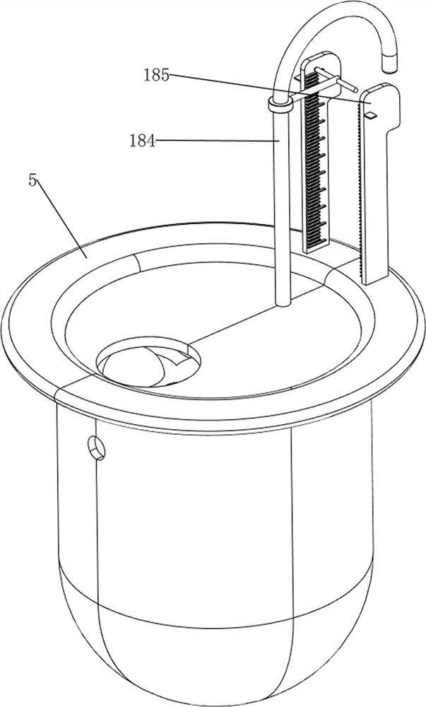
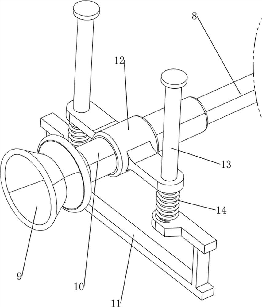
[0035] A height-adjustable wall sprinkling and humidifying device for decoration works, such as Figure 1-6 As shown, it includes a wheel 1, a bottom plate 2, a push rod 3, a first fixed column 4, a water tank 5, a second fixed column 6, a water pump 7, a hose 8, a water spray head 9, a water delivery pipe 10, and a first fixed rod 11. The third fixed column 12, the first sliding rod 13, the first linear spring 14, the anti-splash mechanism 15 and the lifting mechanism 16, the left and right sides of the bottom plate 2 are symmetrically rotated forward and backward, and the wheels 1 are provided, and the top right side of the bottom plate 2 A push rod 3 is fixedly connected, a first fixed column 4 is arranged in the middle of the top of the bottom plate 2, a water tank 5 is arranged on the first fixed column 4, a second fixed column 6 is arranged on the upper left side of the water tank 5, and a second fixed column 6 is arranged on the upper left side of the water tank 5. 6 is...
Embodiment 2
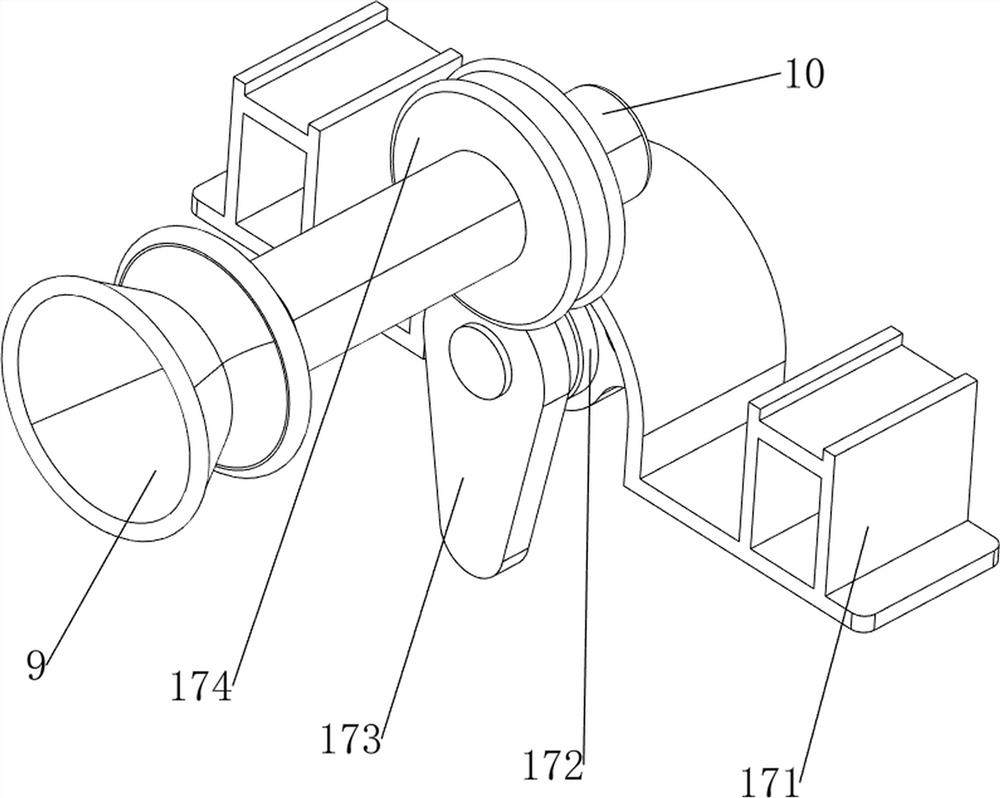
[0040] On the basis of Example 1, such as figure 1 , figure 2 , Figure 7 , Figure 8 , Figure 9 , Figure 10 , Figure 11 , Figure 12 , Figure 13 , Figure 14 and Figure 15 As shown, a transposition mechanism 17 is also included, and the transposition mechanism 17 includes a fixed plate 171, a motor 172, a cam 173 and a second limit ring 174, and a fixed connection between the screw rod 164 and the sliding sleeve 165 is fixedly connected. A motor 172 is arranged between the plate 171 and the fixing plate 171 , a cam 173 is arranged on the motor 172 , and a second stop ring 174 is arranged on the water delivery pipe 10 .
[0041] Start the motor 172, the motor 172 drives the cam 173 to rotate, and the cam 173 intermittently contacts the second limit ring 174, so that the third fixed column 12, the water delivery pipe 10 and the water spray head 9 move up and down, and the first linear spring 14 Adaptive deformation occurs, so that the water spray area of the w...
PUM
 Abstract
Description
Claims
Application Information