Novel double-valve type continuous circulating valve with clamping device

A technology of clamping device and circulation valve, which is applied in wellbore/well components, earthwork drilling, wellbore flushing, etc., can solve problems such as dangerous accidents, and achieve the effect of improving work efficiency and safety

Active Publication Date: 2021-10-08
SOUTHWEST PETROLEUM UNIV
View PDF17 Cites 0 Cited by
  • Summary
  • Abstract
  • Description
  • Claims
  • Application Information

AI Technical Summary

Problems solved by technology

Solved the technical problems of various dangerous accidents caused by the stoppage of drilling circulation medium

Method used


Image

  • Novel double-valve type continuous circulating valve with clamping device
  • Novel double-valve type continuous circulating valve with clamping device

Examples


Embodiment 1

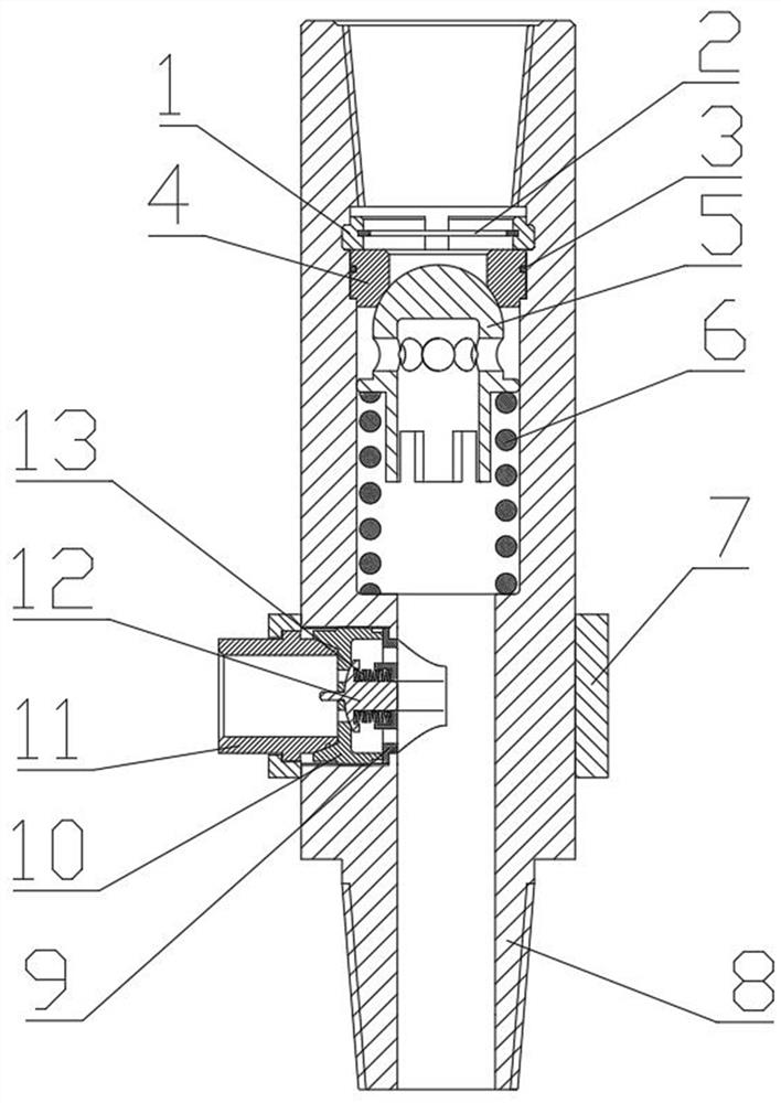
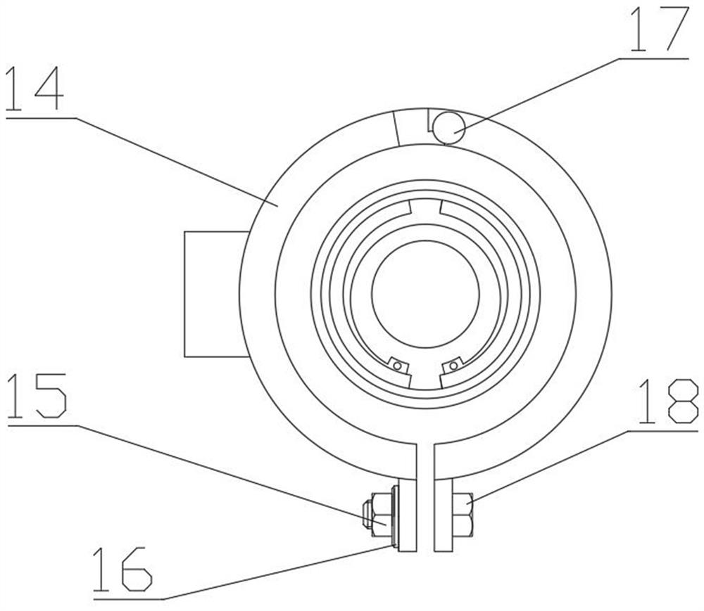
[0044] like Figure 1-Figure 2 Shown:

[0045] This embodiment provides a new double-valve type continuous circulation valve with its own clamping device, including a main through valve 5, a shorting body 8, an intermediate joint 11 and a bypass valve 12, wherein:

[0046] The short-connecting main body 8 is a hollow short shaft structure, and both ends of the short-connecting main body 8 are provided with threaded sections;

[0047] The main valve 5 and the main valve spring 6 are arranged in the short-circuit main body 8;

[0048] The lower end of the main valve 5 is provided with a main valve spring 6, and the upper end is provided with a main valve seat 4;

[0049] The main through valve seat 4, main through valve 5 and main through valve spring 6 are press-fitted inside the shorting main body 8 through the main through valve limiting device 1;

[0050] The lower side of the shorting body 8 is provided with a step hole, the step hole is located below the main valve spri...

Embodiment 2

[0063] This embodiment provides a new double-valve type continuous circulation valve with its own clamping device, including a main through valve 5, a shorting body 8, an intermediate joint 11 and a bypass valve 12, wherein:

[0064] The short-connecting main body 8 is a hollow short shaft structure, and both ends of the short-connecting main body 8 are provided with threaded sections;

[0065] The main valve 5 and the main valve spring 6 are arranged in the short-circuit main body 8;

[0066] The lower end of the main valve 5 is provided with a main valve spring 6, and the upper end is provided with a main valve seat 4;

[0067] The main through valve seat 4, main through valve 5 and main through valve spring 6 are press-fitted inside the shorting main body 8 through the main through valve limiting device 1;

[0068] The lower side of the shorting body 8 is provided with a step hole, the step hole is located below the main valve spring 6, and a bypass valve seat 10 is arrang...


PUM


Abstract

The invention provides a novel double-valve type continuous circulating valve with a clamping device. The novel double-valve type continuous circulating valve comprises a main through valve (5), a pup joint body (8), a middle connector (11) and a bypass valve (12); the main through valve (5) and a main through valve spring (6) are arranged in the pup joint body (8), the main through valve spring (6) is arranged at the lower end of the main through valve (5), and a main through valve seat (4) is arranged at the upper end of the main through valve (5); and the main through valve seat (4), the main through valve (5) and the main through valve spring (6) are arranged in the pup joint body (8) in a pressing manner through a main through valve limiting device (1), a bypass valve seat (10) is arranged at the lower side of the pup joint body (8), the bypass valve (12) is fixed to the bypass valve seat (10) through a bypass valve limiting device (9), the middle connector (11) is arranged at the outer side of the bypass valve limiting device (9), and the middle connector (11) is arranged on the pup joint body (8) in a pressing manner through the clamping device. The technical problem that various dangerous accidents occur due to the fact that circulation of drilling circulation media is stopped is solved.

Description

technical field [0001] The invention relates to the technical field of petroleum drilling, in particular to a novel double-valve continuous circulation valve with a clamping device. Background technique [0002] During the drilling process, when connecting and unloading a single drill pipe or column, the circulation of the drilling circulating medium will be stopped, which will cause bottomhole pressure fluctuations, resulting in well kick, pipe sticking, wellbore instability, overflow, cuttings The occurrence of dangerous accidents such as subsidence. In order to avoid this situation, the continuous circulation valve is mainly used at present to ensure that the drilling circulation medium can circulate smoothly during the replacement of the vertical root and the drill string, so as to effectively overcome the downhole pressure fluctuation caused by the start / stop of the pump, which is very good. Reduce the cost of drilling work, reduce the probability of danger in drilling...

Claims


Application Information

Patent Timeline
Patent Type & Authority Applications(China)
IPC IPC(8): E21B21/10
CPCE21B21/10E21B21/103F16K11/105E21B21/106Y10T137/7856E21B34/00
Inventor 杨火海谢秉宏杨杰刘付喜岳杰阮景鑫刘兴
Owner SOUTHWEST PETROLEUM UNIV
Why Eureka
Try Eureka