Drilling radar system

A drilling radar and coding counter technology, applied in the field of ground exploration engineering, can solve the problem of low detection depth and achieve the effect of increasing the detection depth

Active Publication Date: 2021-10-08
四川华晖盛世探测技术有限公司
View PDF13 Cites 0 Cited by
  • Summary
  • Abstract
  • Description
  • Claims
  • Application Information

AI Technical Summary

Problems solved by technology

[0002] The existing underground detection usually uses ground detection radar. Ground penetrating radar must penetrate the covering layer and weathered zone, and the conductivity value of the covering layer and weathered zone is relatively large, which inhibits the propagation of radar signals. low depth

Method used


Image

  • Drilling radar system
  • Drilling radar system
  • Drilling radar system

Examples


Embodiment Construction

[0041] The following will clearly and completely describe the technical solutions in the embodiments of the present invention with reference to the accompanying drawings in the embodiments of the present invention. Obviously, the described embodiments are only some, not all, embodiments of the present invention. Based on the embodiments of the present invention, all other embodiments obtained by persons of ordinary skill in the art without making creative efforts belong to the protection scope of the present invention.

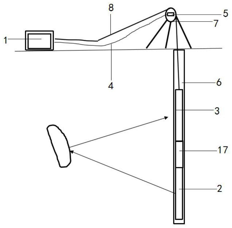
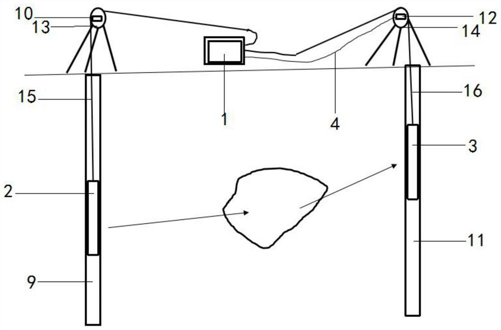
[0042] The object of the present invention is to provide a borehole radar system, which aims at increasing the detection depth and can be applied to the technical field of ground penetrating engineering.

[0043] In order to make the above objects, features and advantages of the present invention more comprehensible, the present invention will be further described in detail below in conjunction with the accompanying drawings and specific embodiments.

[0044] ...


PUM


Abstract

The invention discloses a drilling radar system. The drilling radar system comprises ground equipment and underground equipment; the ground equipment comprises a control unit and a coding counter; the underground equipment comprises a transmitting probe and a receiving probe; the coding counter and the underground equipment are both in communication connection with the control unit; when underground equipment moves, the coding counter is driven to generate a coding counting signal, and the control unit is driven by the coding counting signal to generate a first optical signal and respectively sends the first optical signal to the transmitting probe and the receiving probe; the transmitting probe transmits a detection signal according to the first optical signal; and after receiving the first optical signal, the receiving probe collects a detection signal processed by a target stratum, generates a to-be-measured optical signal and sends the to-be-measured optical signal to the control unit. According to the drilling radar system, a drilling detection mode is set, and the detection depth is increased compared with a ground bottom detection radar.

Description

technical field [0001] The invention relates to the technical field of ground penetrating engineering, in particular to a drilling radar system. Background technique [0002] The existing underground detection usually uses ground detection radar. Ground penetrating radar must penetrate the covering layer and weathered zone, and the conductivity value of the covering layer and weathered zone is relatively large, which inhibits the propagation of radar signals. low depth. Contents of the invention [0003] The object of the present invention is to provide a borehole radar system to increase the detection depth. [0004] To achieve the above object, the present invention provides the following scheme: [0005] A drilling radar system, comprising: ground equipment and downhole equipment; the ground equipment includes: a control unit and an encoding counter; the downhole equipment includes: a transmitting probe and a receiving probe; the encoding counter and the downhole equi...

Claims


Application Information

Patent Timeline
Patent Type & Authority Applications(China)
IPC IPC(8): E21B47/00E21B47/13G01S13/88
CPCE21B47/00E21B47/13G01S13/885
Inventor 刘四新
Owner 四川华晖盛世探测技术有限公司
Why Eureka
Try Eureka